Operating Instructions
LMS5xx
Product description
8013796/ZM63/2017-05-09 © SICK AG · Germany · All rights reserved · Subject to change without notice 19
Chapter 3
The LMS5xx comprises three components:
Sensor head with the opto-electronic acquisition system (housing)
Application module, this defines the functionality of the LMS5xx
System connector with the cloning parameter memory and electrical connections.
The system connector is only removable from LMS500 Lite/PRO Indoor and LMS511
Heavy Duty Outdoor. Due to the cloning parameter memory that is included, the existing
configuration may be transferred to the relevant replacement device automatically on
start-up if, for example, a sensor defect occurs.
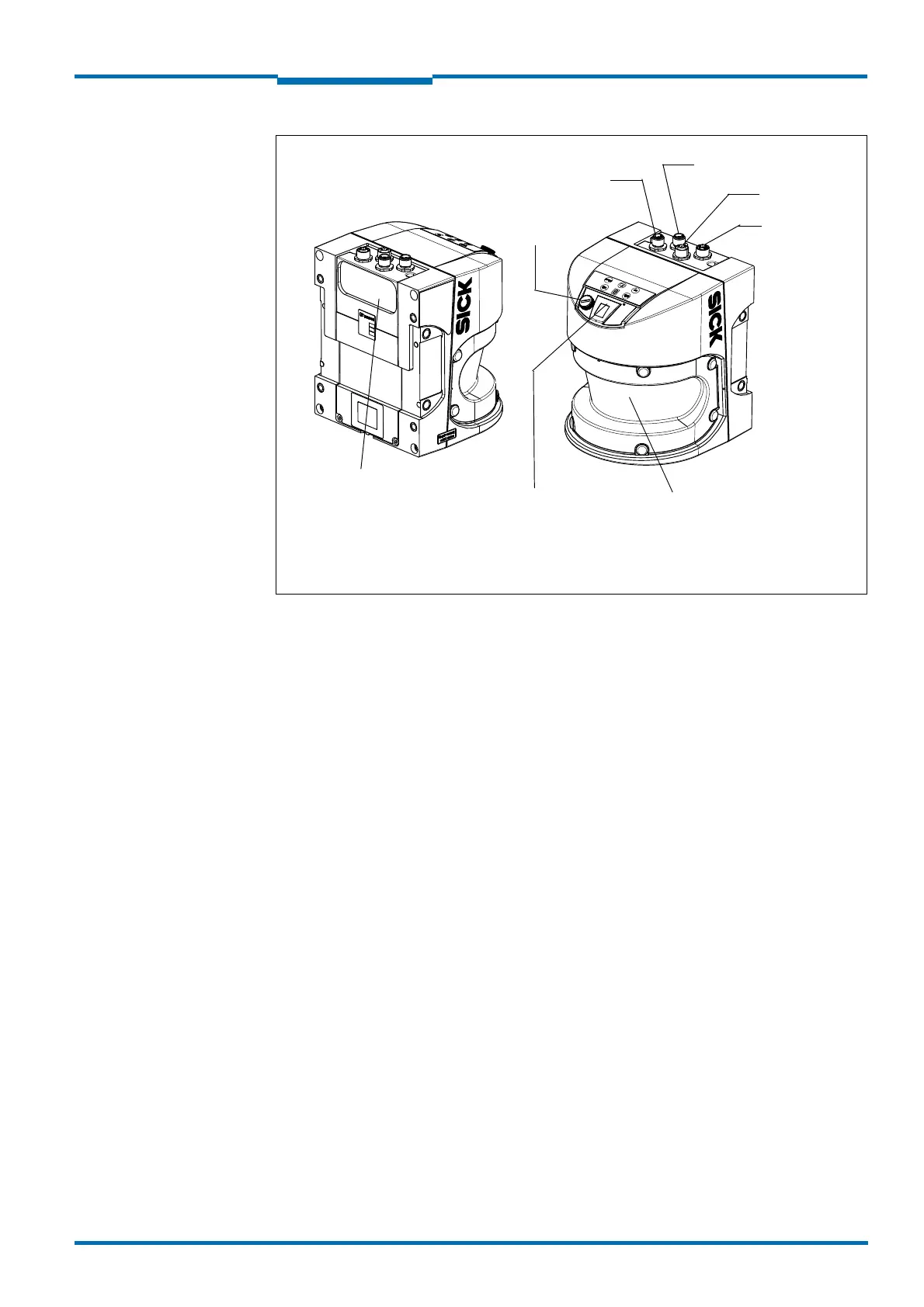
Fig. 3: View of the LMS511/581/531 Outdoor
"Ethernet"
connection
Viewing window
Indicators
"USB"
connection
"Power"
connection
"Data"
1)
connection
"I/O"
2)
connection
1) LMS531 Security: "Inputs" connection
2) LMS531 Security: "Alarm" connection
System connector with cloning
parameter memory.
Removable only from LMS511
Heavy Duty (for replacement
with automatical configuration
of the replacement device).
 Loading...


