Operating Instructions
LMS5xx
Product description
8013796/ZM63/2017-05-09 © SICK AG · Germany · All rights reserved · Subject to change without notice 23
Chapter 3
3.6 Controls and status indicators
3.6.1 User interface
In normal operation the laser measurement sensor operates fully automatically without the
intervention of an operator.
The interactive configuration is carried out using the provided SOPAS ET configuration
software on a PC that must be connected to the LMS5xx.
Use the graphic scan view in SOPAS ET to verify the generated measured values and to
verify the measurement area online.
Important The scan display in SOPAS ET is not performed in real-time but in a limited rate. Therefore
not all measured values are displayed.
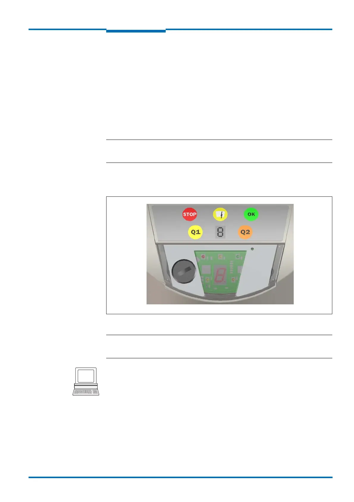
3.6.2 Status indicators
The LEDs and the 7segment display indicate the operational status of the LMS5xx.
Fig. 4: Status indicators
Important On the LMS5xx, along with the standard displays described below, the indication functions
of the LEDs and the 7segment display can be configured in SOPAS ET.
PROJECT TREE, LMS…, PARAMETER, NETWORK/INTERFACES/IOS, DISPLAY.
 Loading...


