Product description
50 © SICK AG · Germany · All rights reserved · Subject to change without notice 8013796/ZM63/2017-05-09
Operating Instructions
LMS5xx Laser Measurement Sensors
Chapter 3
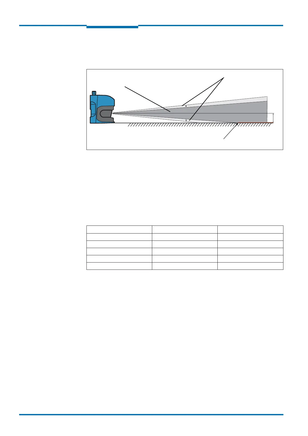
3.14.3 Distance between LMS5xx and the object/surface to be monitored
The laser beam diverges with increasing distance from the LMS5xx. In the scan area the
floor or a wall may then be continuously detected, as the laser beam is incident on it.
Fig. 26: Increase in the size of the beam and safety supplement
The optical axis is used as the reference plane for the distance to be maintained from the
floor or the wall; on a vertically mounted LMS5xx this axis is approx. 116 mm (4.57 in) above
the bottom edge of the housing.
The distance-dependent increase in the size of the beam can be calculated using the
formula:
Beam diameter = distance (mm) × divergence + spot size on front screen
For the values please see Tab. 43: “Data sheet LMS5xx” on page 101.
The following table shows some example values:
For the assessment of whether the laser beam can be incident on an object or the wall, the
distance of half the beam diameter from the optical axis is used.
Recommendation Take into account a safety supplement of approx. 5 mm per meter (0.06 in/ft).
Distance LMS5xx (HR) LMS5xx (SR)
5 m 37 mm 73 mm
10 m 61 mm 133 mm
15 m 85 mm 192 mm
20 m 108 mm 252 mm
50 m 250 mm 609 mm
Tab. 20: Beam diameter on target (diagonal) at different distances from the LMS5xx
Safety supplement
5 mm/m (0.06 in/ft)
From 15 m (49.21 ft) continuous detection
Optical axis
Expanding laser beam
 Loading...


