°
Group 3: C
ables which are a source of interference, such as control cables
for inductive loads, motor brakes
°
Group 4: Cables which are powerful sources of interference, such as output
cables from frequency inverters, welding system power supplies, power
cables
b
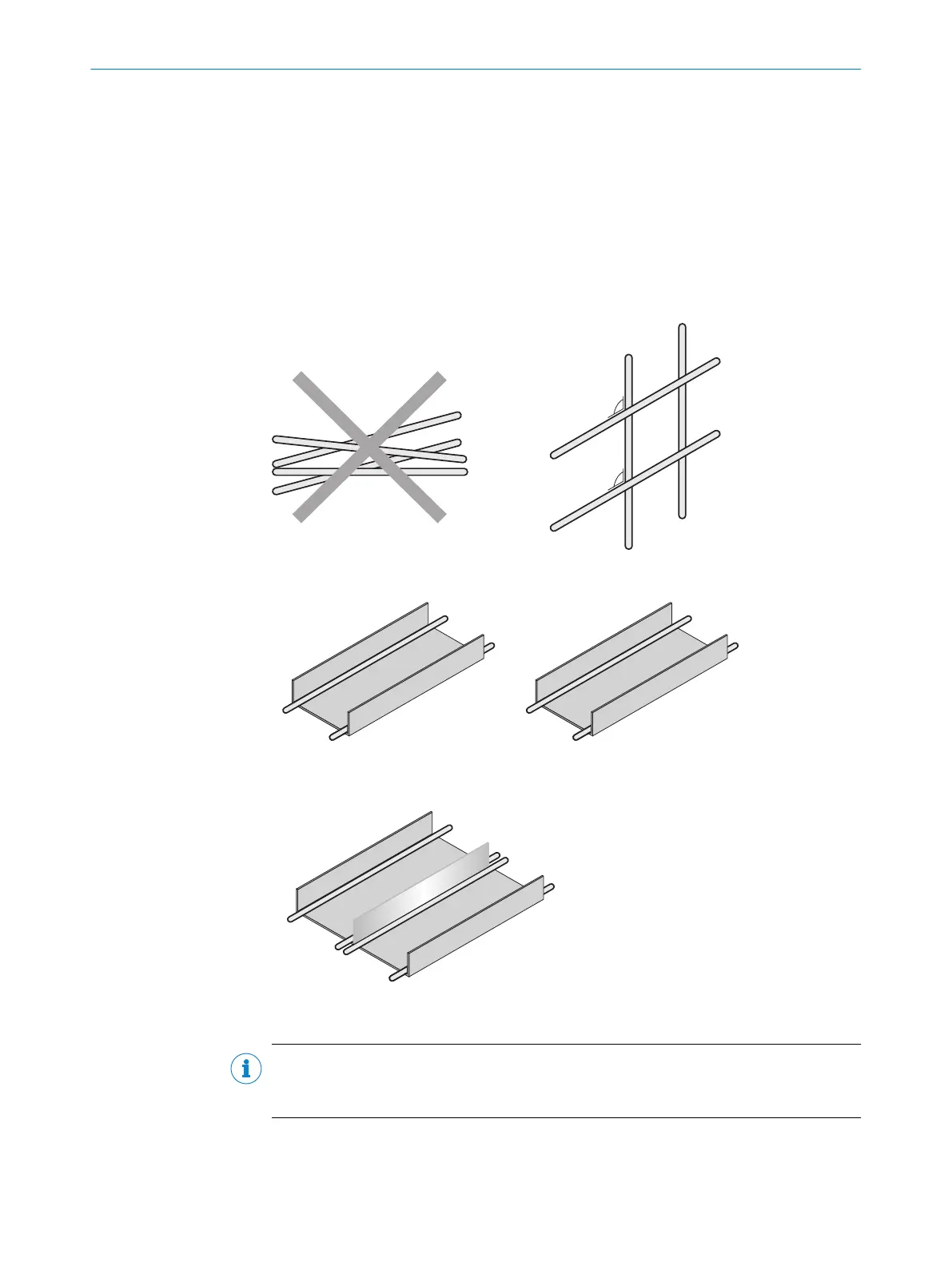
Cables in groups 1, 2 and 3, 4 must be crossed at right angles, see figure 7.
b
Cables in groups 1, 2 and 3, 4 must be routed in different cable channels or
metallic separators must be used, see figure 8 and see figure 9. This applies
particularly where cables of devices with a high level of radiated emission,
such as frequency converters, are laid parallel to sensor cables.
Figure 7: Cross cables at right angles
Figure 8: Ideal laying – Place cables in different cable channels
Figure 9: Alternative laying – Separate cables with metallic separators
NOTE
Pr
e
vent equipotential bonding currents via the cable shield with a suitable earthing
method, see "Safety", page 20.
ELECTRICAL INSTALLATION 6
8025942/2020-07-16 | SICK O P E R A T I N G I N S T R U C T I O N S | MPS-G with 2 / 3 switching points and IO-Link (up to 16 switching points)
21
Subject to change without notice

 Loading...


