EasyManuals Logo

Siemens 3TK28 User Manual

Siemens 3TK28
206 pages
To Next Page IconTo Next Page
To Previous Page IconTo Previous Page
Page #105 background imageLoading...
Page #105 background image
Description of the individual safety relays
3.6 3TK28 safety relays with relay enabling circuits
3TK28 safety relays
Manual, 07/2016, NEB926157502000/RS-AB/003
105
3.6.9.5
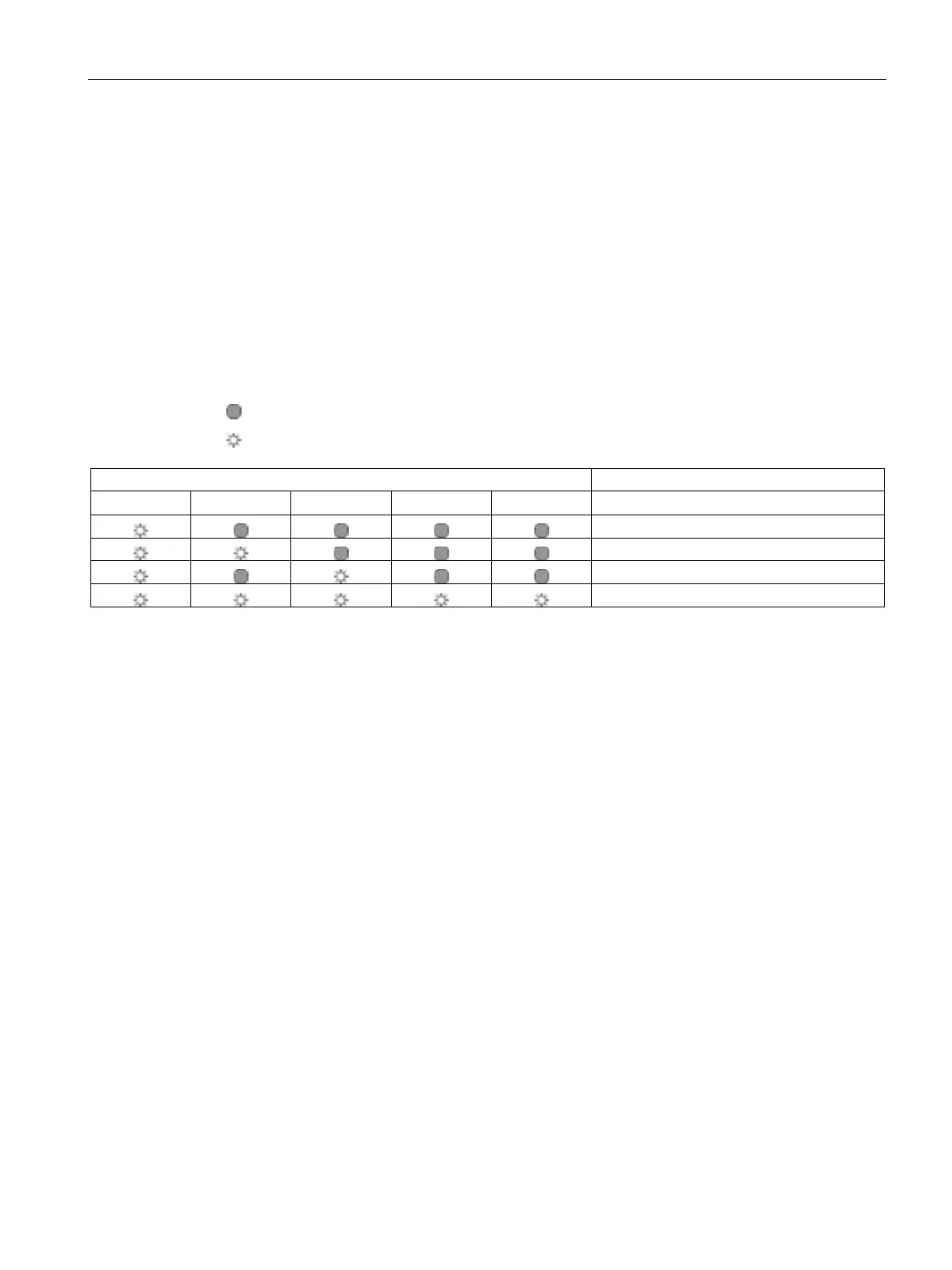
Display of the operating state
The operating state and functioning of the device are indicated by five LEDs:
POWER
S 1 ON
S 2 ON
CHANNEL 1
CHANNEL 2
Operating states of 3TK2834
= off
= on
LED
Operation
POWER
S 1 ON
S 2 ON
Channel 1
Channel 2
Button
Not pressed
Only S1 pressed
Only S2 pressed
S1 and S2 pressed
The device cannot start with the following faults:
Short-circuit, e.g. between the buttons
Defective relay coils
Wire break
Jammed contacts
The output relays do not pick up if
simultaneity (< 0.5 s) is not achieved
only one button is pressed
feedback circuit Y11, Y12 is open.

Table of Contents

Questions and Answers:

Question and Answer IconNeed help?

Do you have a question about the Siemens 3TK28 and is the answer not in the manual?

Siemens 3TK28 Specifications

General IconGeneral
TypeSafety relay
Mounting TypeDIN rail mounting
Type of VoltageAC/DC
Control Supply Voltage at DC24 V
Performance Level According to EN ISO 13849-1PL e
Category According to EN ISO 13849-1Category 4
Mechanical Durability10, 000, 000 cycles
Electrical Durability100, 000 cycles
Protection ClassIP20
Product FunctionSafety Monitoring
Suitability for UseEmergency stop, safety doors
Supply Voltage Frequency50/60 Hz
Control Supply Voltage at AC at 50 Hz24 V
Control Supply Voltage at AC at 60 Hz24 V
Stop Category0
SIL According to IEC 61508SILCL 3
Type of Electrical ConnectionScrew Connection
Rated Control Supply Voltage24 V

Related product manuals