Description of the individual safety relays
3.6 3TK28 safety relays with relay enabling circuits
3TK28 safety relays
Manual, 07/2016, NEB926157502000/RS-AB/003
57
Display of the operating state
The operating state and functioning of the device are indicated by three LEDs:
● POWER
● CHANNEL 1
● CHANNEL 2
Operating states of 3TK2821/24
= off
= on
POWER CHANNEL 1 CHANNEL 2 Line
EMERGENCY
ON Enabling circuit
On Not pressed Pressed Closed
• Relay welded
• Motor contactor welded
• Fault in electronics
Open
Cross-circuit or ground fault in EMERGENCY
STOP circuit (minimum fault current I
Kmin
= 0.5 A;
PTC fuse responds) or no supply voltage
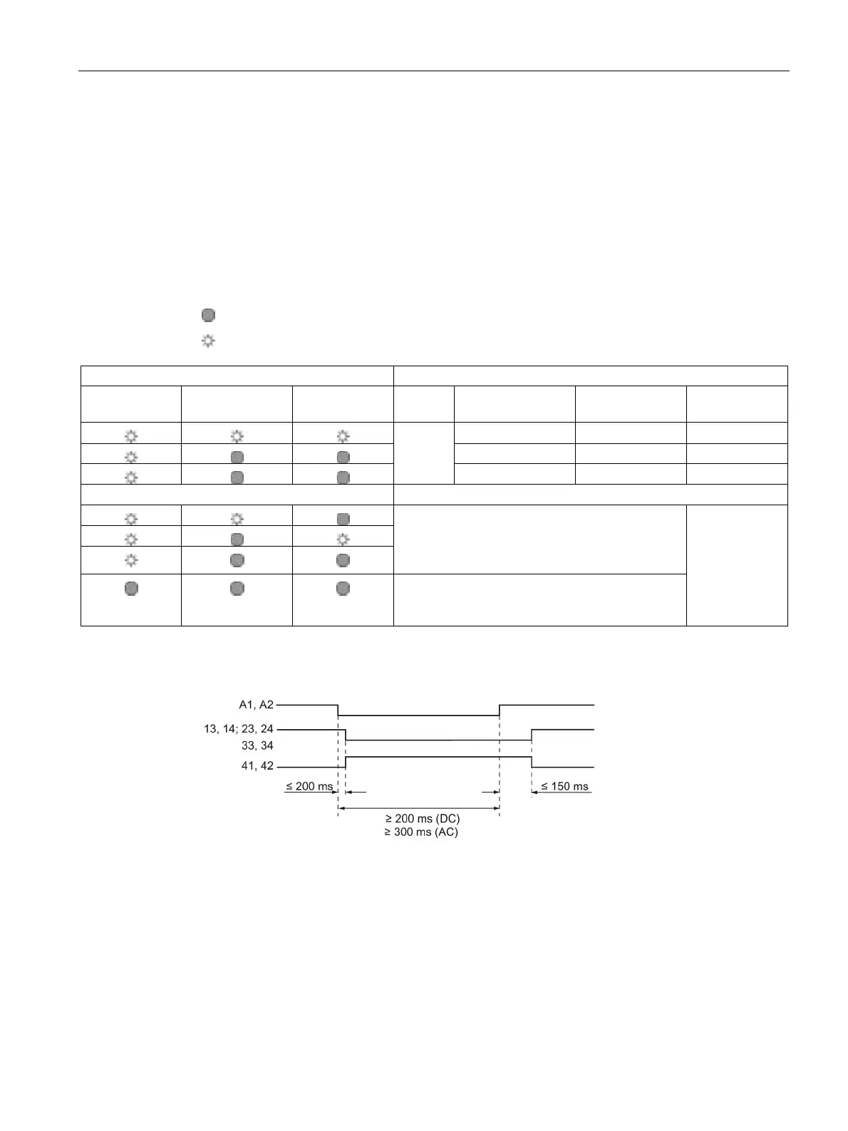
State diagrams 3TK2821 / 3TK2824
Figure 3-14 State diagram 3TK2821/24