Description of the individual safety relays
3.8 3TK28 safety relays with contactor relay enabling circuits
3TK28 safety relays
136 Manual, 07/2016, NEB926157502000/RS-AB/003
3TK28 safety relays with contactor relay enabling circuits
3.8.1
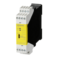
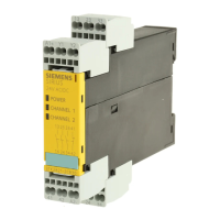
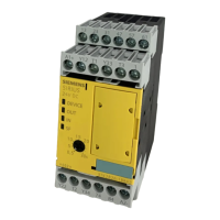
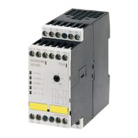
3TK2805 / 3TK2806 safety relays
3.8.1.1
The 3TK2805 / 3TK2806 contactor safety combinations are used in EMERGENCY STOP
circuits and in circuits for monitoring protective equipment, such as safety guards.
Description of function and connection information
Internal control of the contactor safety combination is implemented according to
DIN EN / IEC 60204-1, paragraph 9.4.2.2 so that the function of the safety circuit is retained
in case of a fault in the contactor relay. The supply voltage must meet the requirements of
DIN EN / IEC 60204-1. (Terminal "A2" must be connected to the side of the control circuit
that is connected to the protective circuit.) On each ON and OFF cycle of the machine to be
switched, the contacts of the contactor relays are checked for correct opening and closure.
This is achieved, for example, by:
● Disconnecting and reconnecting the control voltage at the main switch
● Operating and releasing the EMERGENCY STOP device
● Opening and closing the safety guard.
Note
1-channel sensor connection
A 1
-channel control of the contactor safety combination can be implemented by
connecting terminal X6 directly to "A2" a
nd connecting the EMERGENCY STOP device
between terminal X1 and the connected terminals X3; X5.