Description of the individual safety relays
3.7 3TK28 safety relays with solid-state enabling circuits
3TK28 safety relays
Manual, 07/2016, NEB926157502000/RS-AB/003
119
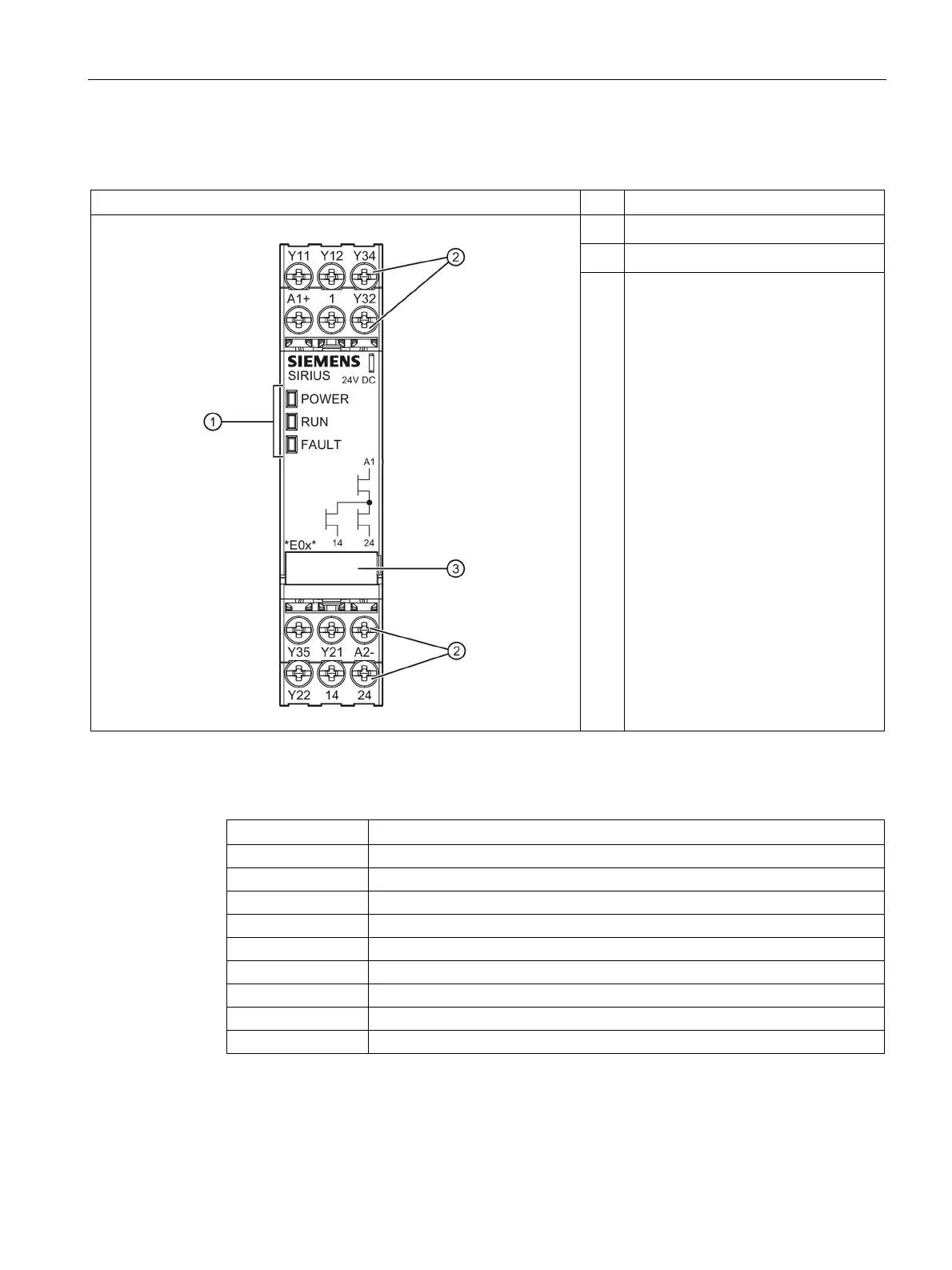
Display LEDs
Removable terminal blocks
③
Labels
Channel 1, EMERGENCY STOP or position switch
Channel 2, EMERGENCY STOP or position switch
with / without cross-circuit detection
Parameterization "single-channel sensor connection"
ON button, feedback circuit