Additional system components
7.3 Sensor Module Cabinet-Mounted SMC30
SINAMICS DCM DC Converter
212 Operating Instructions, 12/2018, A5E34763375A
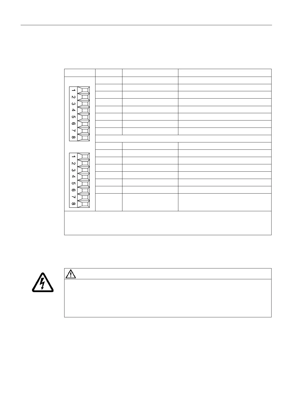
X521/X531 alternative encoder system interface
Table 7- 16 X521/X531 alternative encoder system interface
X521
X531
Inverse incremental signal A
4 B* Inverse incremental signal B
Inverse reference signal R
Temperature sensor KTY84-1C130
Temperature sensor KTY84-1C130
8 Data* Inverse SSI data
Max. connectable cross-section: 1.5 mm
2
Measuring current via the temperature sensor connection: 2 mA
When unipolar HTL encoders are used, A*, B*, and R* on the terminal block must be jumpered with
1)
Because the physical transmission properties are more robust, the bipolar connection should
always be used. The unipolar connection should only be used if the encoder type does not output
Electric shock due to unconnected cable shields
Hazardous touch voltages can occur through capacitive cross-coupling due to unconnected
cable shields.
• Attach the cable shield to the component via terminals for the encoder system
connection.
 Loading...
