Additional system components
7.5 Terminal Module TM31
SINAMICS DCM DC Converter
244 Operating Instructions, 12/2018, A5E34763375A
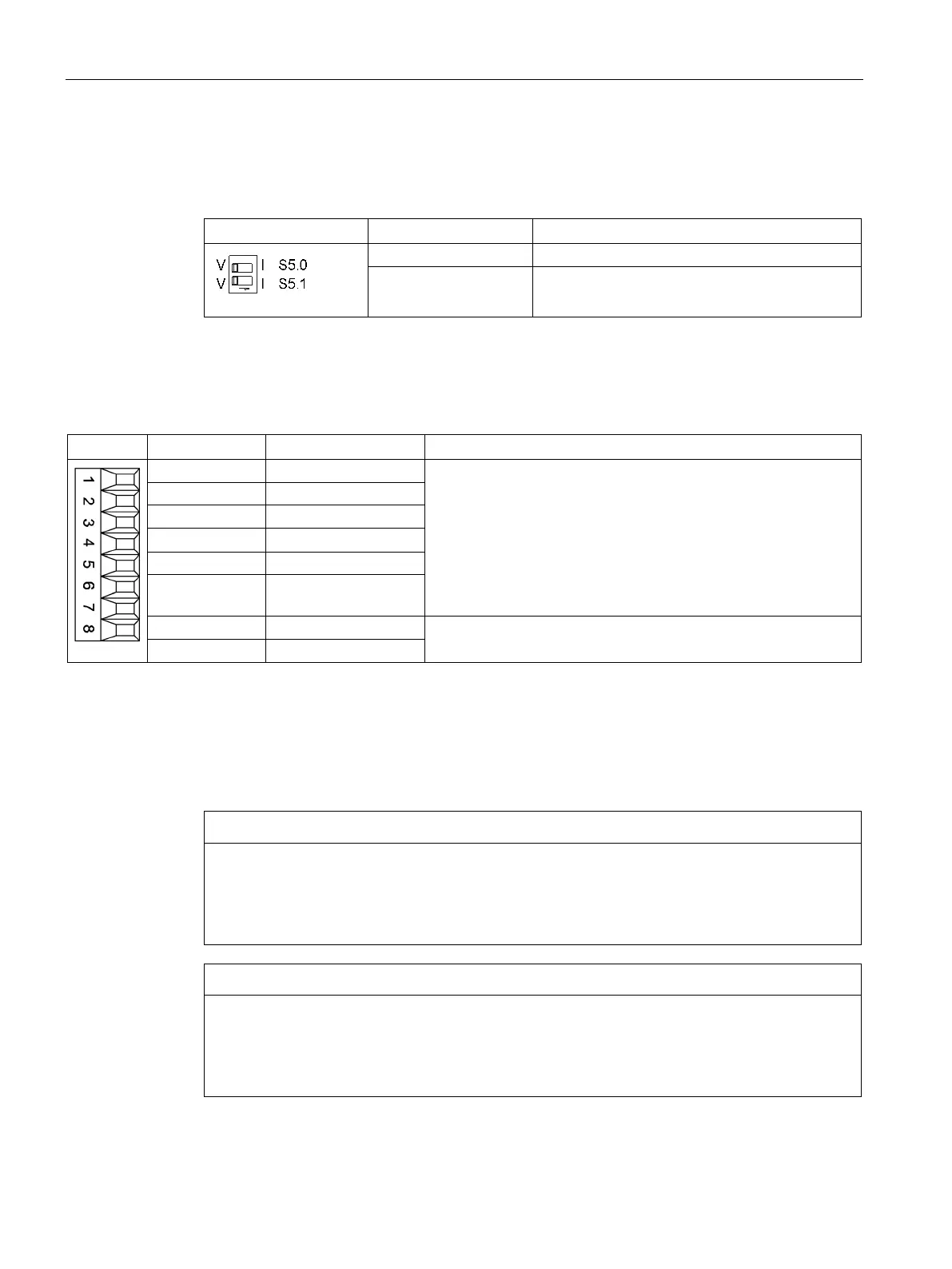
Analog inputs current/voltage switch
Table 7- 37 Current/voltage selector switch S5
Switchover of voltage (V)/current (I) Al0
S5.1 Switchover of voltage (V)/current (I) Al1
X522 analog outputs/temperature sensor
Table 7- 38 X522 terminal strip
You can set the following output signals using parameters:
-10 V to 10 V (max. 3 mA)
: 4 to 20 mA (max. load resistance ≤ 500 Ω)
-20 mA to 20 mA (max. load resistance ≤ 500 Ω)
: 0 to 20 mA (max. load resistance ≤ 500 Ω)
Resolution: 11 bits + sign
Sustained short-circuit-proof
4 AO 1V+
6 AO 1C+
2)
Temperature sensor KTY84-1C130 / PT1000 / PTC
Measuring current via temperature sensor connection: 2 mA
2)
AO xV: Analog output voltage; AO xC: Analog output current
Accuracy of the temperature measurement:
- KTY: ±7 °C (including evaluation)
- PT1000: ±5 °C (PT1000 tolerance class B according to EN 60751 including evaluation)
- PTC: ±5 °C (including evaluation)
Damage or malfunctions through impermissible voltage values
If the back EMF is impermissible then damage and malfunctions may occur on the
components.
• The back EMF at the outputs may only be in the range between -15 V and +15 V.
Damage to motor in the event of incorrectly connected KTY temperature sensor
If a KTY temperature sensor is connected with incorrect polarity, it is not possible to detect
when the motor overheats. Overheating can cause damage to the motor.
• Connect a KTY temperature sensor with the correct polarity.
 Loading...
