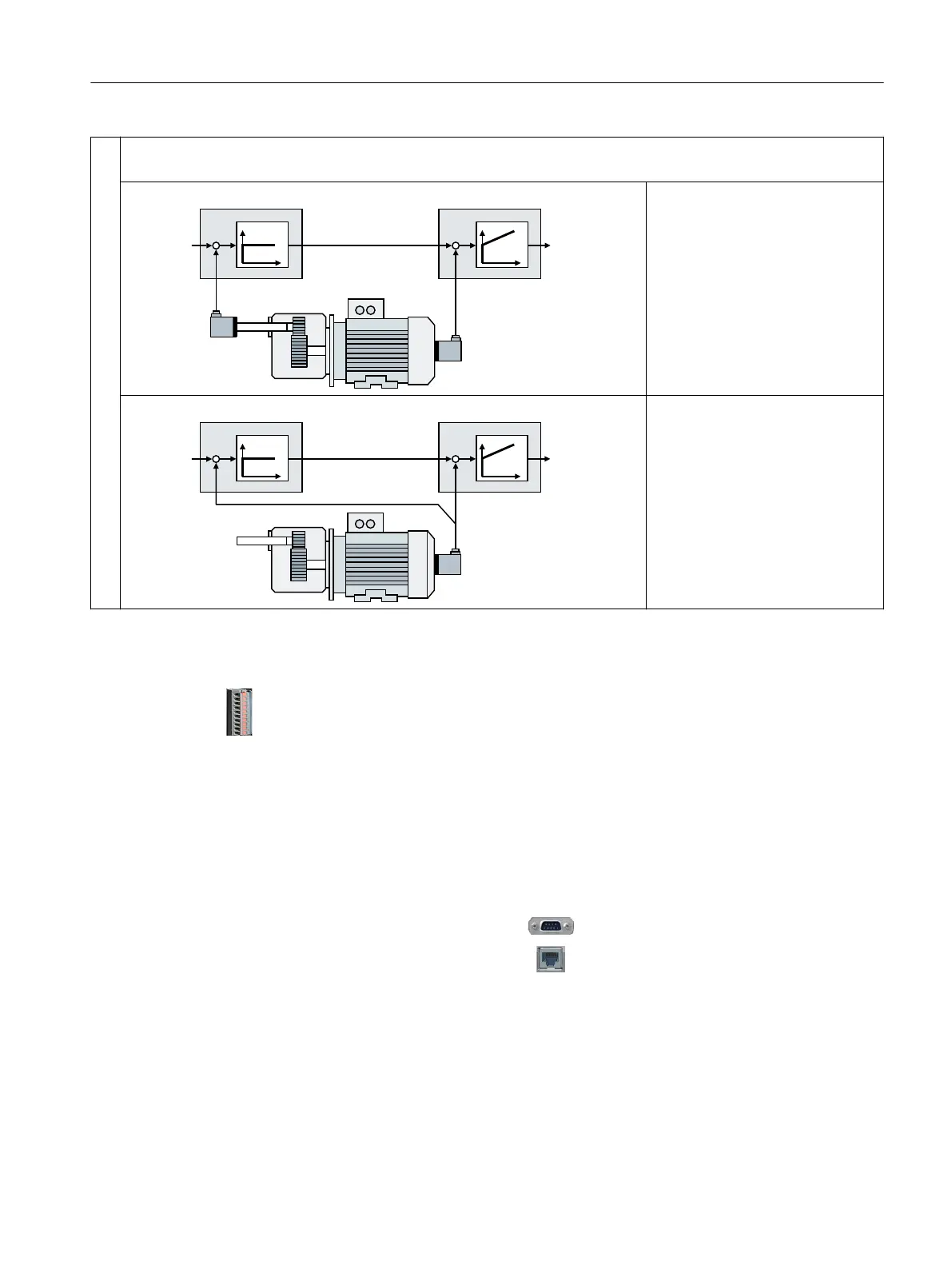
③ Position controller and speed controller use dierent encoders.
The encoder for the speed controller must be mounted on the motor shaft.
(QFRGHU
(QFRGHU
6SHHGFRQWUROOHU3RVLWLRQFRQWUROOHU
7RUTXH
VHWSRLQW
3RVLWLRQ
VHWSRLQW
.
3
7
1
.
3
Compared to the other options of
encoder assignment, this congura‐
tion provides the best control re‐
sults.
(QFRGHUDQGHQFRGHU
66,HQFRGHUZLWKLQFUHPHQW
WUDFNV
6SHHGFRQWUROOHU3RVLWLRQFRQWUROOHU
7RUTXH
VHWSRLQW
3RVLWLRQ
VHWSRLQW
.
3
7
1
.
3
Depending on the gear ratio, restric‐
tions regarding the accuracy of the
position control.
Not suitable for position control in
the case of mechanical slip on the
load side.
Example
An HTL encoder is connected to terminal strip -X136.
You have the following options in this case:
• You use the HTL encoder for the speed controller and operate the drive without position
control.
• You use the HTL encoder both for the speed controller and for the position controller ①.
• You operate the drive with encoderless speed control and use the encoder for the position
controller ②.
• You use the HTL encoder at the termi‐
nal strip only for the speed controller
and a second encoder for the position
controller ③.
You can connect the second encoder for
the position controller either to the D-sub
connector ‑X2100 or to the DRIVE-CLiQ
interface ‑X100.
Permissible encoder combinations
Basic positioner
Function Manual, 09/2020, FW V4.7 SP13, A5E34257659B AG 17

 Loading...


