Structure of the PROFIBUS DP Parameter Assignment and Configuration Frame
144
DP/AS-Interface Link 20E
Release 11/2002
C79000-G8976-C138–04
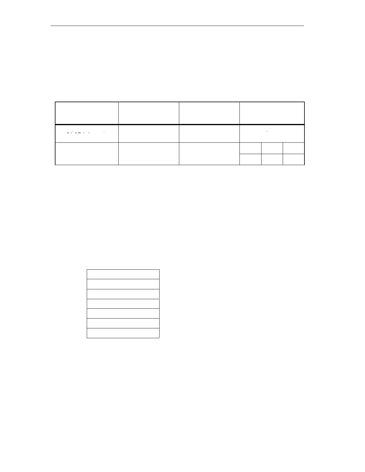
Configuration Frame
The structure of the configuration frame depends on whether you require I/O
operation with up to 31 AS-i slaves or with up to a maximum of 62 AS-i slaves in
the extended addressing mode.
Operation Number of output
bytes on the DP
master
Number of input
bytes on the DP
master
Configuration Frame
I/O operation for up to
16 16 Byte 0 :
31 AS-i slaves
1)
3F
H
I/O operation in the
32 32 Byte 0 Byte 1 Byte 2
ex
en
e
a
ress
ng
mode
C0
H
1F
H
1F
H
1) The default configuration (response to a Get_Cfg frame prior to initialization by the DP master)
is the configuration with I/O operation for up to 31 AS-i slaves.
Structure of the Parameter Assignment Frame
The parameter assignment frame of the DP/AS-Interface Link 20E is 17 bytes
long. It consists of a 7 byte standard section complying with EN 50170 and a
further 10 byte long field with additional parameters for the DP/AS-Interface Link
20E.
Standard Section
Byte 0 Station status, see /6/
Byte 1 Watchdog factor 1, see /6/
Byte 2 Watchdog factor 2, see /6/
Byte 3 Min. T
SDR
, see /6/
Byte 4
80H
Vendor ID, high byte, see /6/
Byte 5
98H
Vendor ID, low byte, see /6/
Byte 6 Group ID, see /6/