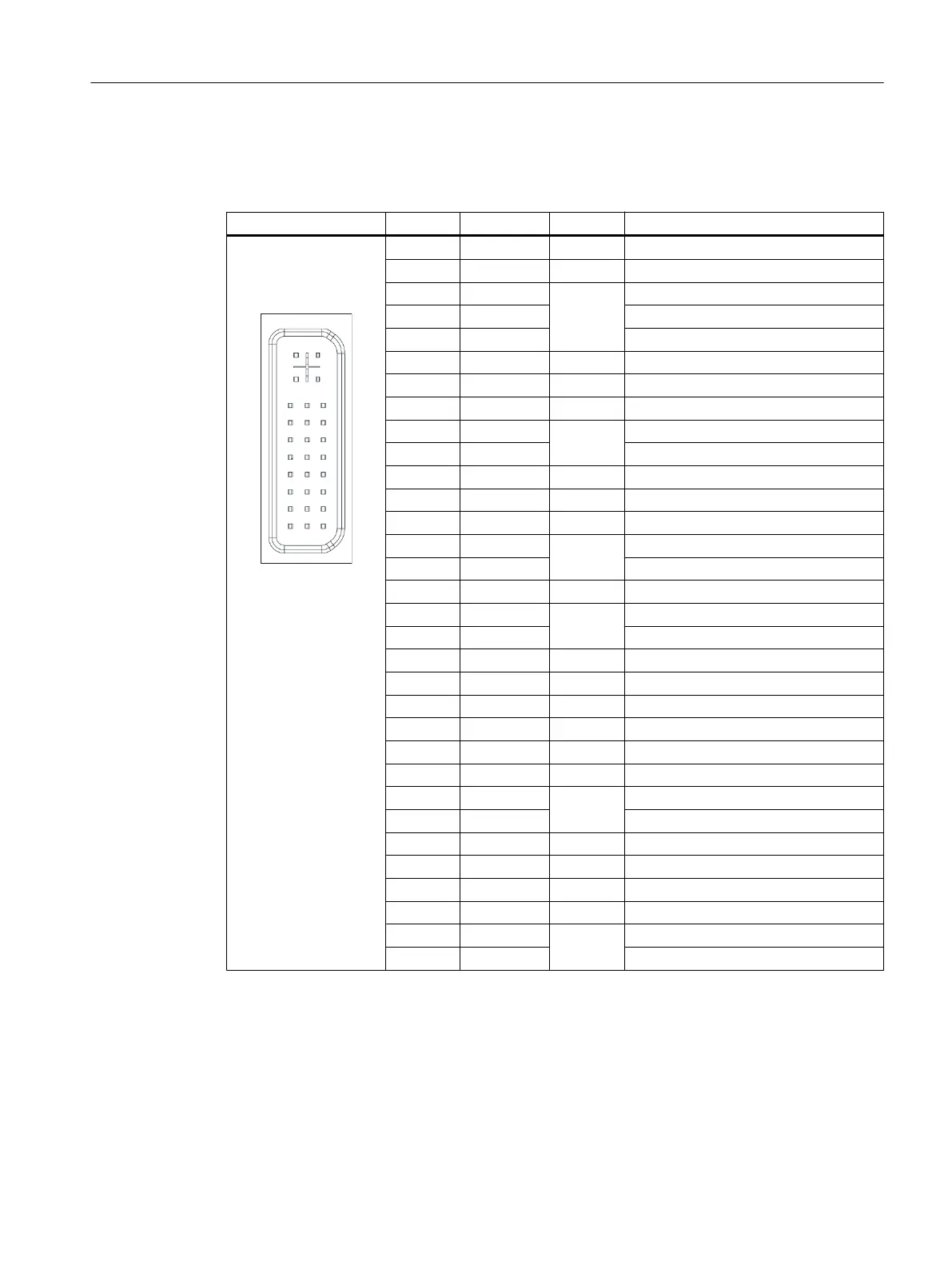
Table 1-7 Assignment of the PROFIBUS DP / MPI interface
Connector Pin Name Type Remark
1,2 N.C. - Not connected
3 LTG_B B Signal line B of MPI module
4 RTS_AS I Control signal for receive data current. Signal 1
active if directly connected control is sending.
5 M5EXT V Return line (GND) of 5 V supply. Current load
from a load of 90 mA max. connected between
P5EXT and M5EXT.
6 P5EXT V 5 V supply (current load see M5EXT)
7 N.C. - Not connected
8 LTG_A B Signal line A of MPI module
9 RTS_PG O RTS signal of MPI module; signal is "1", when
PG is sending
Shield - On connector housing
PROFIBUS DP interface
Connector type: 9-pin sub-D socket
Max. data transmission rate: 12 Mbit/s
Max. cable length: 100 m
Table 1-8 Assignment of the PROFIBUS DP interface
Connector Pin Name Type Remark
1,2 N.C. - Not connected
3 RS_DP B RS-485 differential signal
4 RTS_DP O Request To Send
5 M5EXT V 5 V external ground
6 P5EXT V 5 V external potential
7 N.C. - Not connected
8 XRS_DP B RS-485 differential signal
9 N.C. - Not connected
Ethernet RJ45 interface
Connector type: Standard RJ45 socket
Max. data transmission rate: 10/100/1000 Mbit/s
Max. cable length: 100 m
General information and networking
1.3 Connecting
Handheld Terminal HT 8
Manual, 07/2015, A5E36371621B-AB 27
 Loading...


