4
Creating a ShopTurn Program 08/2005
4
♥ Siemens AG, 2005. All rights reserved
4-140 SINUMERIK 840D sl Operation/Programming ShopTurn (BAT) – 08/2005 Edition
During the choosing of the traversing path, ShopTurn always
considers the tool tip, i.e. the elongation of the tool is not taken into
consideration. Be careful therefore that the retraction planes are
correspondingly far away from the workpiece.
Tailstock
If your machine has a tailstock, you can expand the retraction area
again, so that a collision with the tailstock will be avoided when
traversing the axes.
Enter the retraction plane XRR of the tailstock in absolute dimensions.
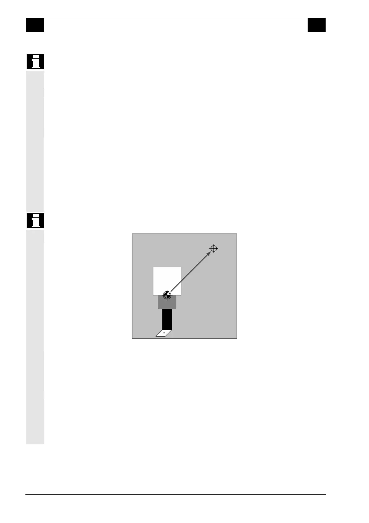
Tool change point
The revolver with its zero-point travels to the tool change point and
then positions the desired tool in machining position. The tool change
point must be so far outside the retraction area that no tool projects
into the retraction area when it is moving.
Either you establish the current tool position as a tool change point
(teaching a tool change point) or you must input the coordinates of the
tool change point XT and ZT directly into the parameter screen form.
Teaching the tool change point is only possible if you have selected
the machine coordinate system (MKS).
Be sure that the tool change point is relative to the zero-point of the
revolver and not to the tool tip.
Tool change point
Safety distance
The safety distance SC defines how close the tool can approach the
workpiece in rapid traverse.
You must input the safety distance incremental dimensions without a
preceding symbol.
Speed limits
If you want to machine the workpiece with a constant cutting speed,
ShopTurn must increase the spindle speed once the workpiece
diameter becomes smaller. Since the speed cannot be increased at
will, you can set a speed limit for the main spindle (S1) and for the
counter-spindle (S3), depending on the shape, size, and material of
the workpiece or collet.
 Loading...


