Appendices
Modbus VERIS H8035/H8036 Emulation
96
Building Technologies 125-202
06/06/2017
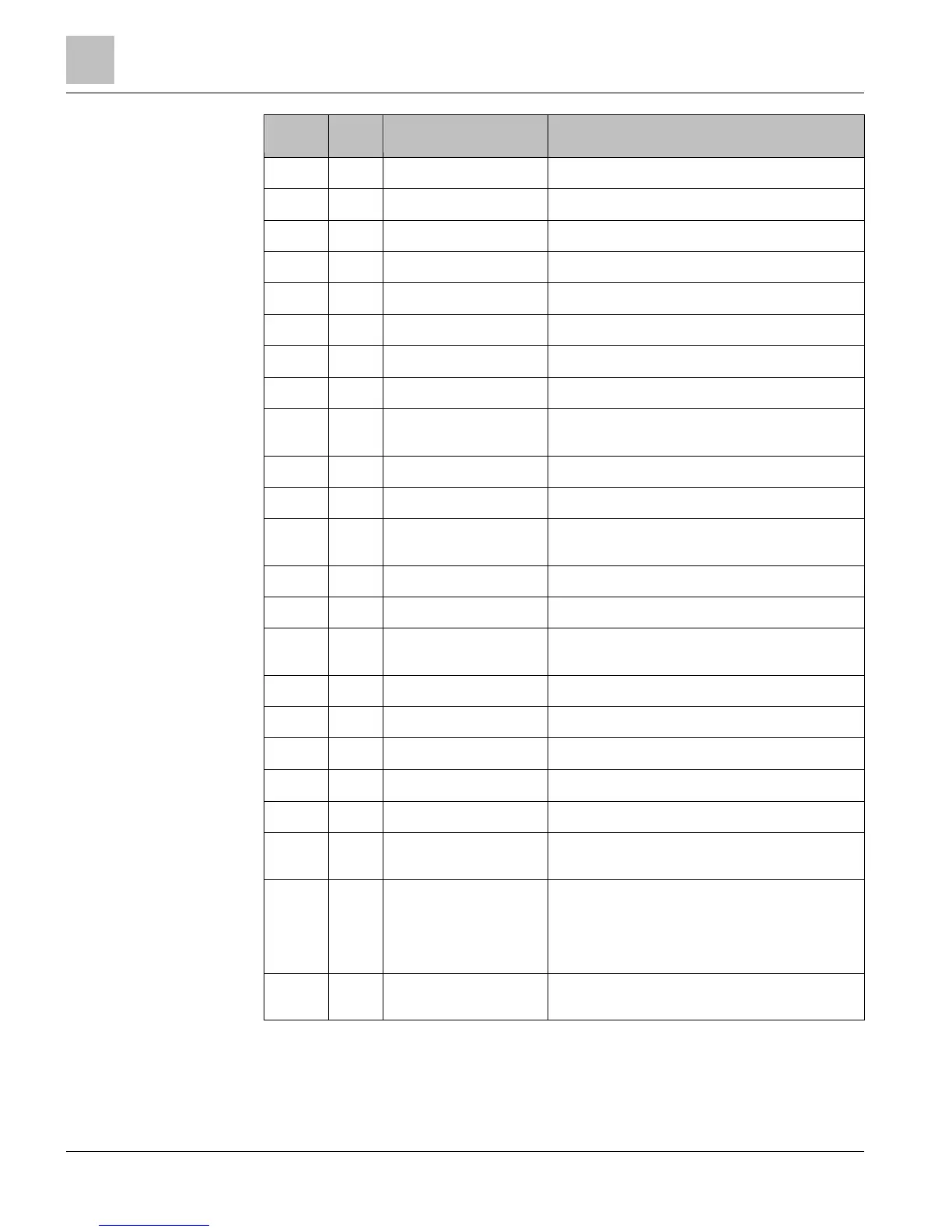
Modbus
Register
Offset ViewPoint Name Description
40005 4 kVA System System Apparent Power (kVA)
40006 5 Apparent PF System System Apparent Power Factor (PF)
40007 6 Volts Line to Line Avg Average Line to Line Voltage
40008 7 Volts Line to Neutral Avg Average Line to Neutral Voltage
40009 8 Amps System Avg Average current of all phases
40010 9 kW L1 Individual Phase True Powers (kW, 3 values)
40011 10 kW L2 "
40012 11 kW L3 "
40013 12 Apparent PF L1 Individual Phase Apparent Power Factors (PF, 3
values)
40014 13 Apparent PF L2 "
40015 14 Apparent PF L3 "
40016 15 Volts L1 to L2 Individual Phase to Phase Voltages (Volts, Delta, 3
values)
40017 16 Volts L2 to L3 "
40018 17 Volts L1 to L3 "
40019 18 Volts L1 to Neutral Individual Phase to Neutral Voltages (Volts, Wye, 3
values)
40020 19 Volts L2 to Neutral "
40021 20 Volts L3 to Neutral "
40022 21 Amps L1 Individual Phase Currents (Amps, 3 values)
40023 22 Amps L2 "
40024 23 Amps L3 "
40025 24 kW System Avg Equals KWH_SYSTEM_L&M ÷ (TimeSinceReset_L&M
seconds /3600 seconds/Hr) (resettable)
40026 25 kW Demand System Min System Minimum Demand (kW, resettable), It displays
the default value after a CAM until 1 demand window
elapses. After a power cycle or CPU reset, the value is
not reset and does not update again until 1 demand
window elapses.
40027 26 kW Demand System Max System Maximum Demand (kW, resettable). Behaves
as 40026.