Checking the assemblies 2 - 3
Siemens AG SPR8-125.061.02 Page 3 of 8 POLYMOBIL Plus
Medical Engineering Rev. 01 01.00 TD SD 24
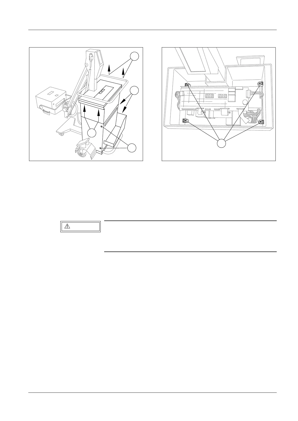
• Remove the four Allen screws at the bottom of the switchbox cover (2/Fig.4) and remove
the cover.
• After removing the four panel screws (3/Fig.4), remove the bottom cover at the front with
the cassette tray.
• Remove the four screws of the top housing (4/Fig.5)
• To stay clear of the exposure guide holder, tilt the housing forward and lift it up to
remove it.
Always measure the actual voltage present with the DVM at test
points -VCC and + VCC on the D 960 inverter board or (more
accessible) on the D 970 capacitor board at the + connection
point of capacitor C3 and on the right side of fuse F3.
Fig. 4 Fig. 5
3
3
2
2
4
WARNING