29 / 92
Siemens…………………….RDF301, RDF301.50..., RDF600KN, RDF600KN/VB, RDF600KN/S Basic Documentation CE1P3171en
Smart Infrastructure 2020-02-21
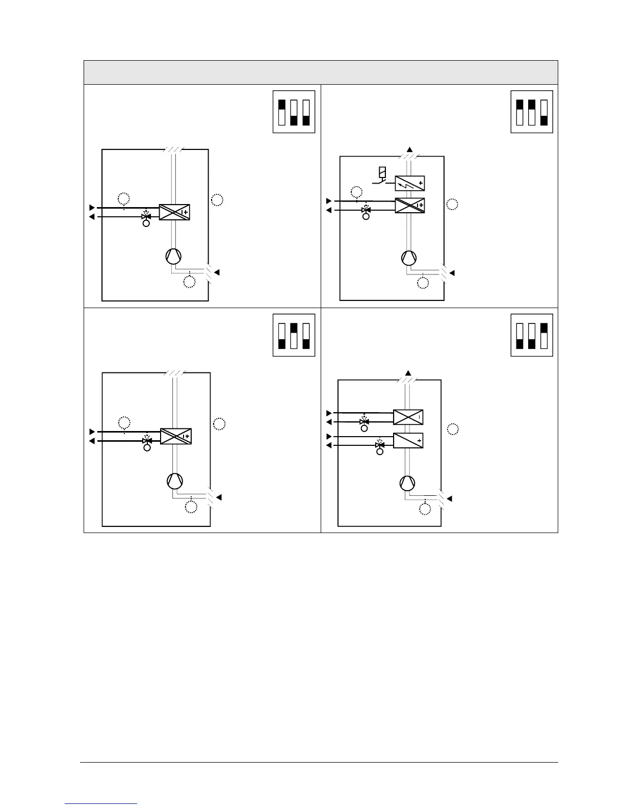
3.4.1 Applications for fan coil systems
Application and output signal, DIP switches, diagram
· 2-pipe fan coil unit ON/OFF
(heating or cooling)
1
ON
2 3
· 2-pipe fan coil unit with el. heater
(heating or cooling) ON/OFF
1
ON
2 3
3076D20
(B1)
M1
Y1
T
B2
T
T
(B1)
Y1
M1
3171D21
T
B2
YE
T
(B1)
T
(B1)
· 2-pipe fan coil unit 3-position
(heating or cooling)
1
ON
2 3
· 4-pipe fan coil unit ON/OFF
(heating and cooling)
·
1
ON
2 3
3076D20
(B1)
M1
Y1
T
B2
T
T
(B1)
T
Y2
Y1
M1
3076D22
(B1)
T
(B1)
Y1 Heating or heating/cooling valve
actuator
B1 Return air temperature sensor or external room
temperature sensor (optional)
Y2 Cooling valve actuator B2 Changeover sensor (optional)
YE Electric heater M1 1-speed or 3-speed fan*)
N1 Thermostat
Note : On RDF301 and RDF301.50, it is recommended that the fan is running in
deadzone, i.e. P60=0, or using a return air- or external temperature sensor.
Legend

 Loading...