42 / 92
Siemens………………………RDF301, RDF301.50..., RDF600KN, RDF600KN/VB, RDF600KN/S Basic Documentation CE1P3171en
Smart Infrastructure 2020-02-21
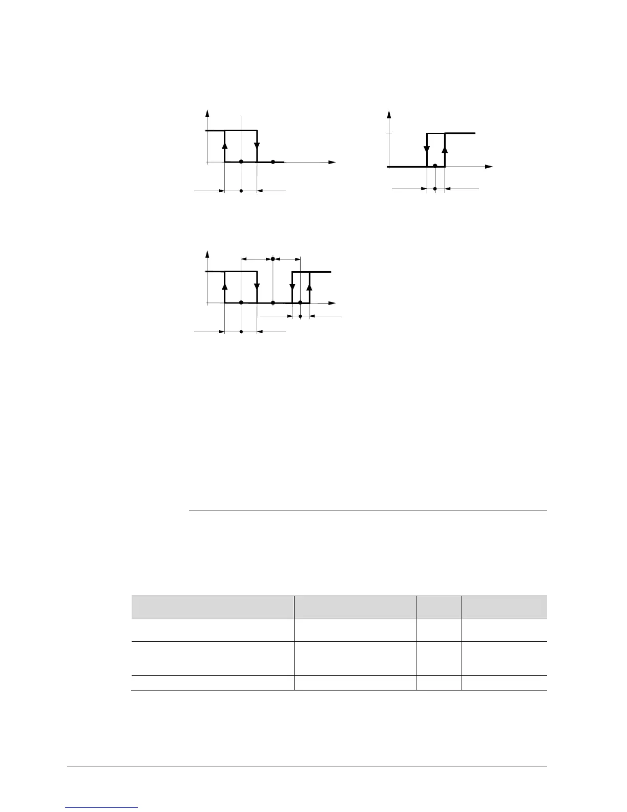
The diagrams below show the control sequence for 2-position control.
Heating mode with manual selection
(P01 = 2)
Cooling mode with manual selection
(P01 = 2)
0
w
T[°C]
½ SDH ½ SDH
Y1
½ SDC
0
½ SDC
w
T[°C]
Y2
Heating and cooling mode (P01 = 04)
½ SDC
0
½ SDC
w
T[°C]
Y2
½ SDH ½ SDH
Y1
½ x
dz
½ x
dz
T[°C] Room temperature
w Room temperature setpoint
Y1 Control command "Valve" or "Comp." (H)
Y2 Control command "Valve" or "Comp." (C)
SDH Switching differential "Heating" (P30)
SDC Switching differential "Cooling" (P31)
X
dz
Dead zone (P33)
· The diagrams only show the PI thermostat’s proportional part.
· For the fan sequence see section 3.8.
Setting the sequence and the control outputs
Refer to section 3.4, section 3.6.1, and section 3.7.
3.6.6 Chilled / heated ceiling and radiator applications*
For chilled / heated ceiling and radiator,
· set the corresponding basic application
· disable the fan (P52)
The following applications are available:
Application for
Set basic application See
Sequences
Chilled / heated ceiling with
changeover
2-pipe 3.6.3
H ( \ )
C (
)
Chilled / heated ceiling & el heater
(cooling only: disable el heater
via P13)
2-pipe and electric heater 3.6.4
El H + H ( 7\ \ )
El H + C ( 7\ / )
C (
)
Chilled ceiling and radiator
4-pipe 3.6.5
H + C ( \ / )
* Not applicable for RDF301 and RDF301.50.
Note:

 Loading...