30 / 92
Siemens………………………RDF301, RDF301.50..., RDF600KN, RDF600KN/VB, RDF600KN/S Basic Documentation CE1P3171en
Smart Infrastructure 2020-02-21
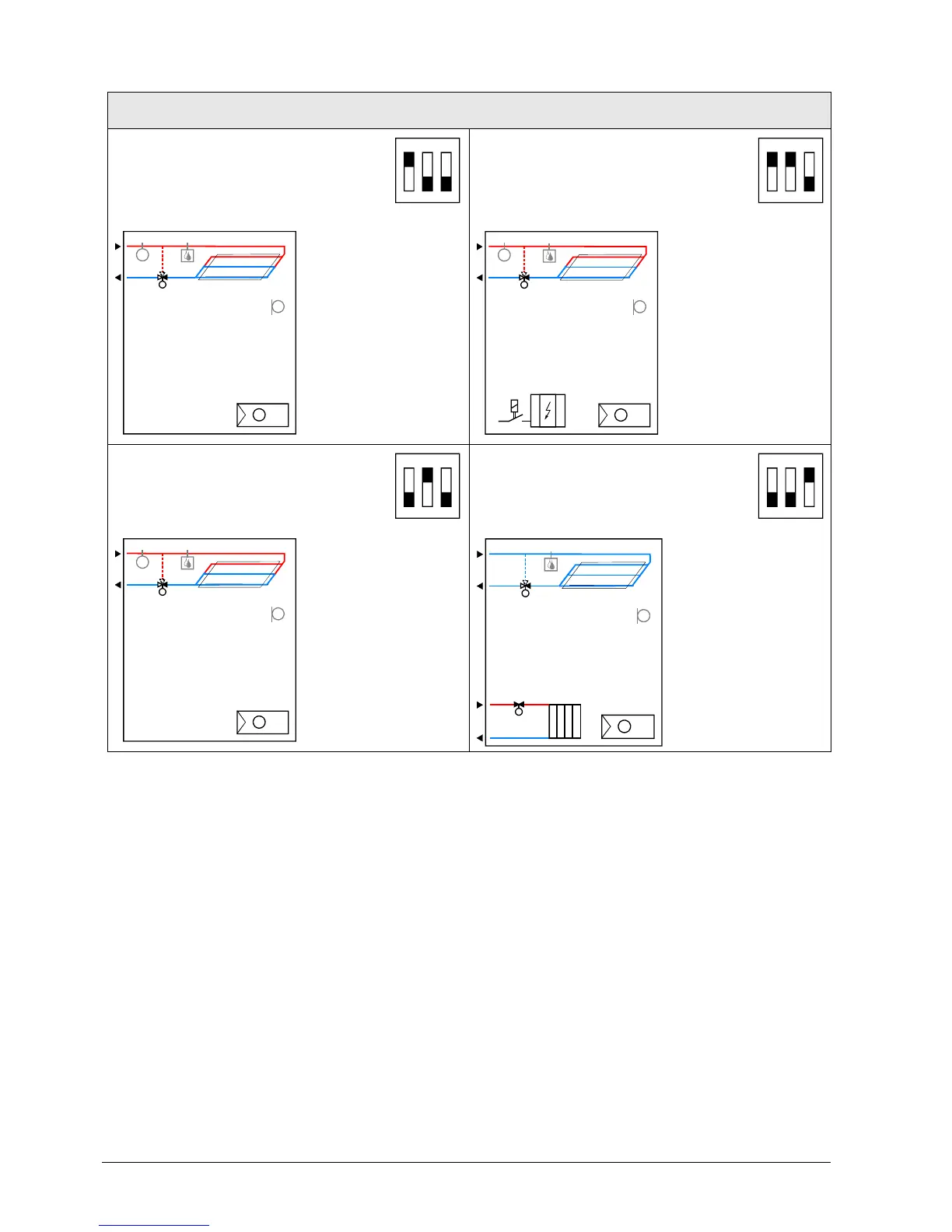
3.4.2 Applications for Universal systems*
Application and output signal, DIP switches, diagram
· Chilled / heated ceiling
(heating or cooling)
1
ON
2 3
· Chilled / heated ceiling with electric
heater (heating or cooling) ON/OFF
1
ON
2 3
N1
T
B1
T
B2
T
D3
Y1
N1
T
YE
B1
T
B2
T
D3
Y1
· Chilled / heated ceiling
(heating or cooling)
·
1
ON
2 3
· Chilled ceiling and radiator ON/OFF
(heating and cooling)
1
ON
2 3
N1
T
B1
T
B2
T
D3
Y1
N1
T
B1
T
D3
Y1
YR
Y1 Heating or heating/cooling valve
actuator
B1 Return air temperature sensor or external room
temperature sensor (optional)
YR Radiator valve actuator B2 Changeover sensor (optional)
YE Electric heater M1 1-speed or 3-speed fan
N1 Thermostat D3 Dewpoint sensor
* Universal applications are not applicable for RDF301 and RDF301.50.
Legend

 Loading...