87 / 94
Siemens RDF301, RDF301.50..., RDF600KN, RDF600KN/S Basic Documentation CE1P3171en
Building Technologies 2017-12-07
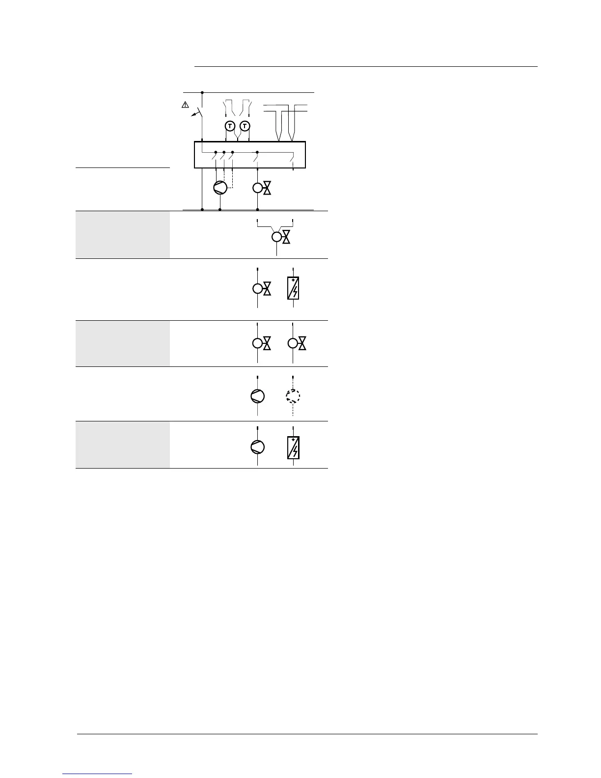
6.2 Connection diagrams
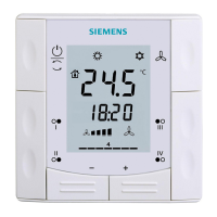
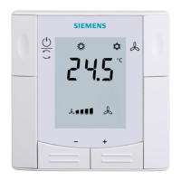
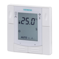
N1 Room thermostat
RDF301... , RDF600KN…
M1 1- or 3-speed fan
Y1 Valve actuator, 2- or 3-position
Y1, Y2 Valve actuator, 2-position
E1 Electric heater
C1, C2 1-stage compressor
S1, S2 Switch (keycard, window contact,
presence detector, etc.)
B1, B2 Temperature sensor (return air
temperature, external room
temperature, changeover sensor,
etc.)
CE+ KNX data +
CE- KNX data –
2-pipe, 2-position
2-pipe, 3-position
– Y11 = Open
– Y21 = Close
2-pipe and electric
heater
4-pipe
– Y1 = Heating
– Y2 = Cooling
1-stage compressor
– C1 = Heating
and / or
– C2 = Cooling)
1-stage compressor
and electric heater
L
N
10 A
L
N
Y11
Y21
AC 230 V
X1
M
X2
N1
M1
Y1
5(2)A
max.
5(2)A
max.
B2
S2
B1
S1

 Loading...