RDF301, RDF301.50..., RDF600KN
With a 2 pipe application
changeover signal (via local sensor or bus), or fixed according to the selected
control sequence (P01 = heating (0) / cooling (1)).
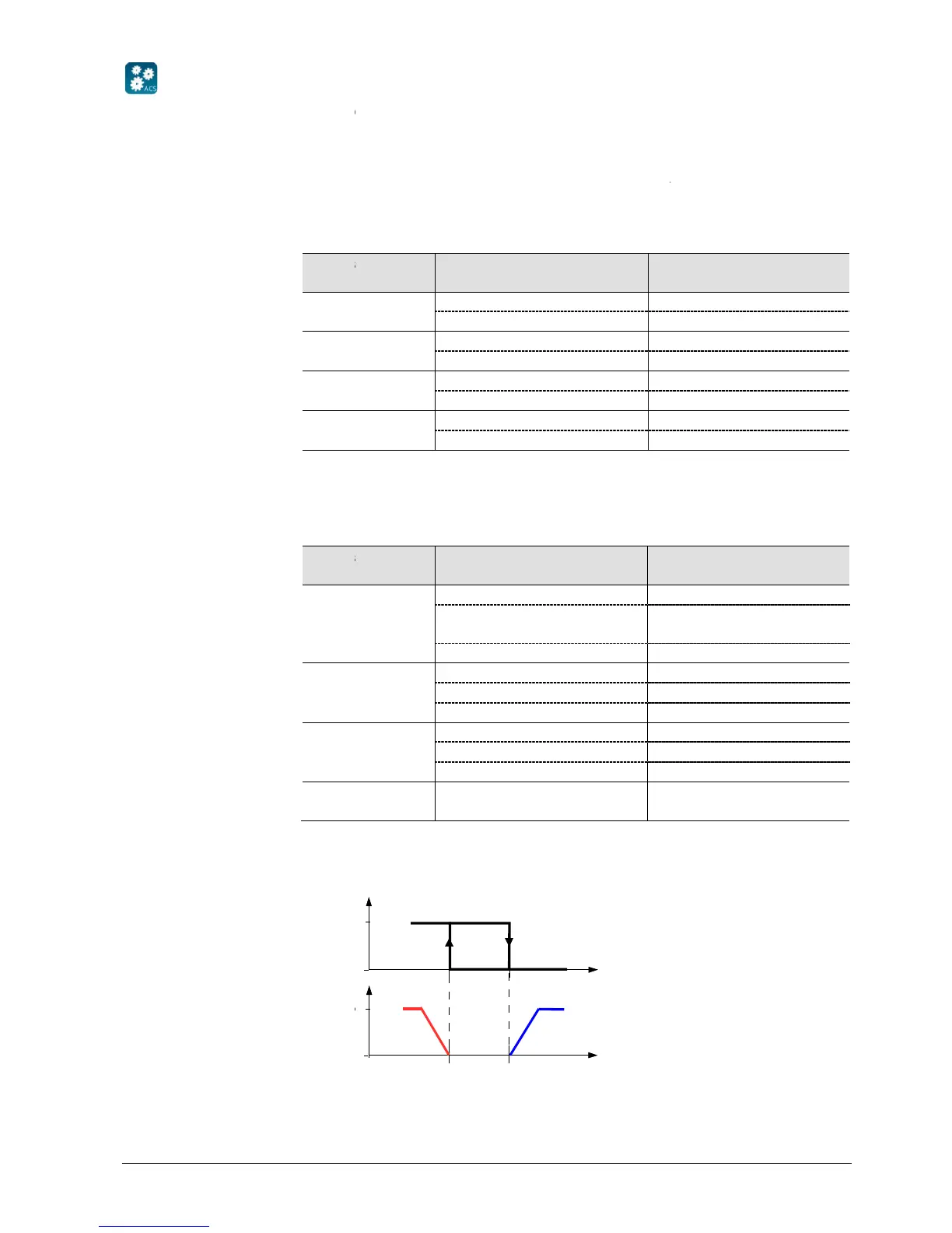
The value of the output as a function of the room temperature is shown in the
following diagram in case of a heating and cooling system:
ACS
Heating OR cooling
Heating AND cooling
RDF301, RDF301.50..., RDF600KN
(heating or cooling) of the thermostat
The last active mode is dis
dead zone or temperature control is disabled.
With a 2 pipe application
, the control sequence state
section 3.6.3) and by the state
changeover signal (via local sensor or bus), or fixed according to the selected
control sequence (P01 = heating (0) / cooling (1)).
State changeover / conti-
nuous heating or cooling
C
-pipe, 2-pipe with electric heater, and 2-
pipe with radiator application
depends on the application mode and on the heating /
No temperature control active
The value of the output as a function of the room temperature is shown in the
following diagram in case of a heating and cooling system:
The last active mode is dis
dead zone or temperature control is disabled.
changeover signal (via local sensor or bus), or fixed according to the selected
pipe with radiator application
depends on the application mode and on the heating /
The value of the output as a function of the room temperature is shown in the
following diagram in case of a heating and cooling system:

 Loading...