Communication Ports
4.3Serial Ports
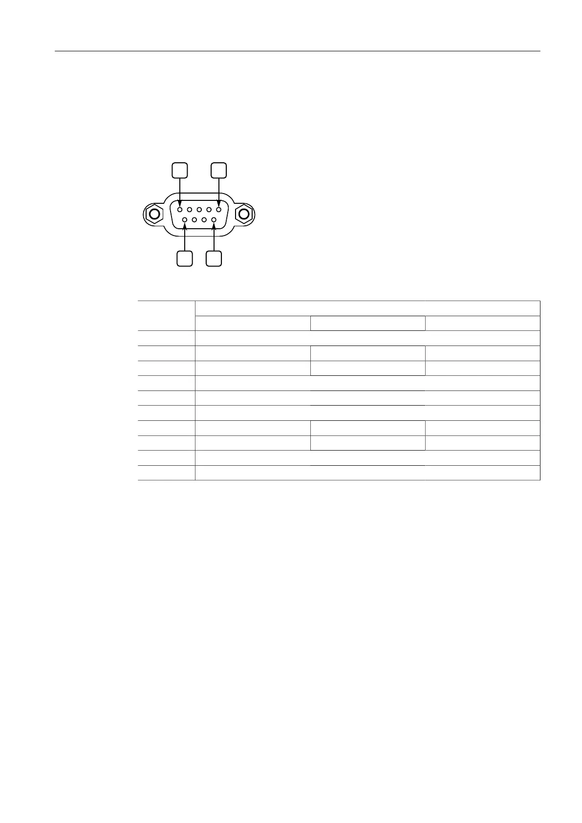
The following is the pin-out description for DB9 serial ports:
Serial DB9 Port
Figure4.3 Serial DB9 Port Pin Configuration
ModePin
RS-232 RS-422 RS-485
1 Reserved (Do Not Connect)
2 RX
a
RX-
3 TX
a
TX- RX-/TX-
4 Reserved (Do Not Connect)
5 Common (Isolated) Ground
6 Reserved (Do Not Connect)
7 RTS TX+ RX+/TX+
8 CTS RX+
9 Reserved (Do Not Connect)
Shield Chassis Ground
a
In RS-232 mode, ports transmit to DTE (Data Terminal Equipment) devices on pin 2 and receive from
DTE devices on pin 3.
Each RS-485 port can communicate with multiple RS-485 devices by wiring devices
together in sequence over a single twisted-pair with transmit and receive signals on
the same two wires (half duplex). For reliable, continuous communication, adhere to
the following guidelines:
• To minimize the effects of ambient electrical noise, use shielded cabling.
• The correct polarity must be observed throughout a single sequence or ring.
• The number of devices wired should not exceed 32, and total distance should be
less than 1219 m (4000 ft) at 100 kbps.
• The Common terminals should be connected to the common wire inside the
shield.
• The shield should be connected to earth ground at a single point to avoid loop
currents.
• The twisted pair should be terminated at each end of the chain.
The following shows the recommended RS485 wiring.
32
RUGGEDCOM RX1400
Installation Manual, 09/2019, C79000-G8976-1103-13
 Loading...