5-102
System Manual
C79000-G8576-C199-06
With jumper J6, you can set all V.24 receivers so that you only require
positive-going signals (positive voltage region).
123
J6 All received signals must be at
V.24 signal level.
All received signals can be in the
positive voltage region.
With the submodule 0AA23, bridge 6 has no function; all signals can lie in
the positive range (corresponds to bridge setting 2-3).
With jumper J9, CTS can be set permanently to quiescent potential, i.e.
switched through from the front connector.
123
J9 CTS at quiescent potential CTS at
pin 5
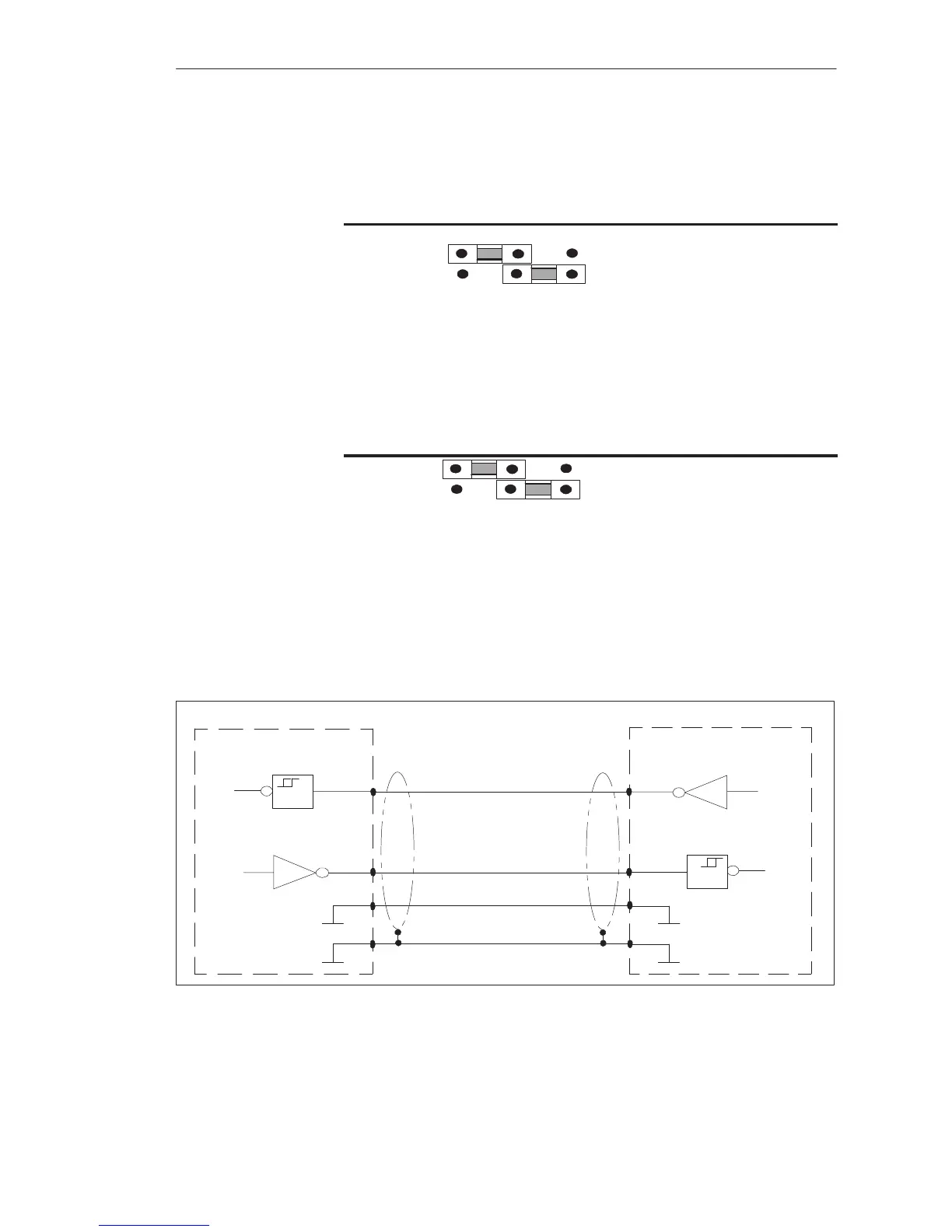
Standard cables for connecting the V.24 submodule of the CPU to the partner
station are available from Siemens in various lengths, up to16 m.
Order numbers and lengths can be found in the ordering information.
Connecting cable for CPU, CP 524, CP 525, CP 544
CPU, CP524/525, CP544
RxD
7
Shield
2
7
TxD
Receiver Transmitter
TxD
2
3
RxD
ReceiverTransmitter
Housing, GND Housing, GND
3
11
CPU, CP524/525, CP544
Figure 5-16 V.24 Submodule: Connecting Cable for CPU, CP 524, CP 525, CP 544
Standard Connect-
ing Cables of the
V.24 Submodule
CPUs, Memor
Cards, Memor
Submodules, Interface Submodules
 Loading...

