5-107
System Manual
C79000-G8576-C199-06
The TTY submodule feeds in the current (20 mA) via jumpers in the
connector of the standard connecting cable. The 24 V required for generation
of loop current is taken from the power supply of the PLC. In the quiescent
state, with a correct loop current connection, there should be a flow of 20 mA
(= logic 1). When the current is interrupted there is a logic 0.
The following applies to the TTY signals:
Logic 0 is represented by: no current
Logic 1 is represented by: current (20 mA)
A maximum of 9600 bps is permissible for data transmission with the TTY
submodule.
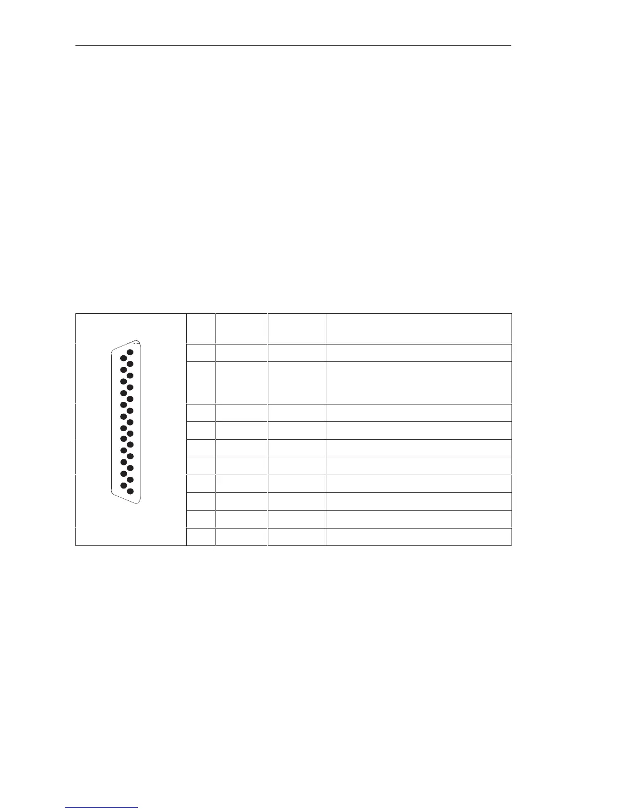
Shown in the figure are the pin assignments of the 25-pin subminiature
D-type connector in the front plate of the TTY submodule:
Pin Designa-
tion
Current
direction
Remarks
25
13
1 Shield
9 24 V
external
This connection is changed over between
24 V internal and 24 V external with
jumper J3 (see next page).
10 + TxD ²
12 + 20 mA ³ Current source, transmitter
13 + RxD ²
14 – RxD ³
14
16 + 20 mA ³ Current source, receiver
1
19 – TxD ³
21 – 20 mA ² Current return
24 – 20 mA ² Current return
² : Input
³ : Output
Data Transmission
Rate
Pin Assignments
of the TTY
Submodule
CPUs, Memor
Cards, Memor
Submodules, Interface Submodules
 Loading...

