5-108
System Manual
C79000-G8576-C199-06
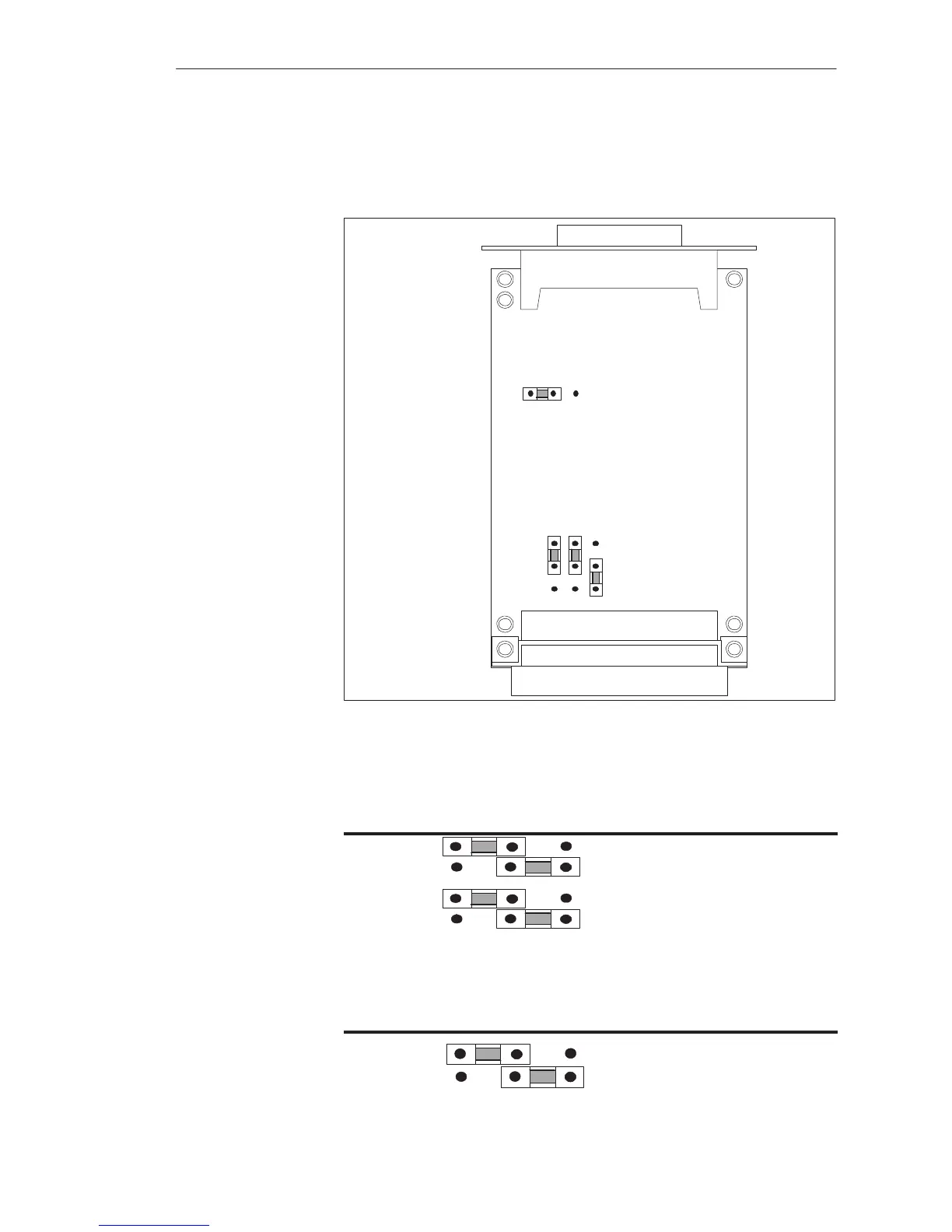
When the TTY submodule is delivered, the jumpers are set as shown in the
following figure. As a rule, therefore, you can use the TTY submodule
immediately.
Backplane Connector
J3
J4
J2
J1
123
Front Connector
25-Pin Sub. D-Type
1
2
3
Figure 5-21 TTY Submodule: Jumper Settings when Delivered
The polarity of the transmit and receive data is changed over with jumpers J1
and J2:
123
J1 Transmit data negated
Transmit data in normal polarity
J2 Receive data in normal polarity
Receive data negated
The 24 V source voltage for generation of the loop current can be allocated
with jumper J3:
123
J3 24 V will be applied from Pin 9 of
the sub. D connector
24 V will be applied from the
backplane connector (internally)
Jumper Settings
on the TTY
Submodule
CPUs, Memor
Cards, Memor
Submodules, Interface Submodules
 Loading...

