8-48
System Manual
C79000-G8576-C199-06
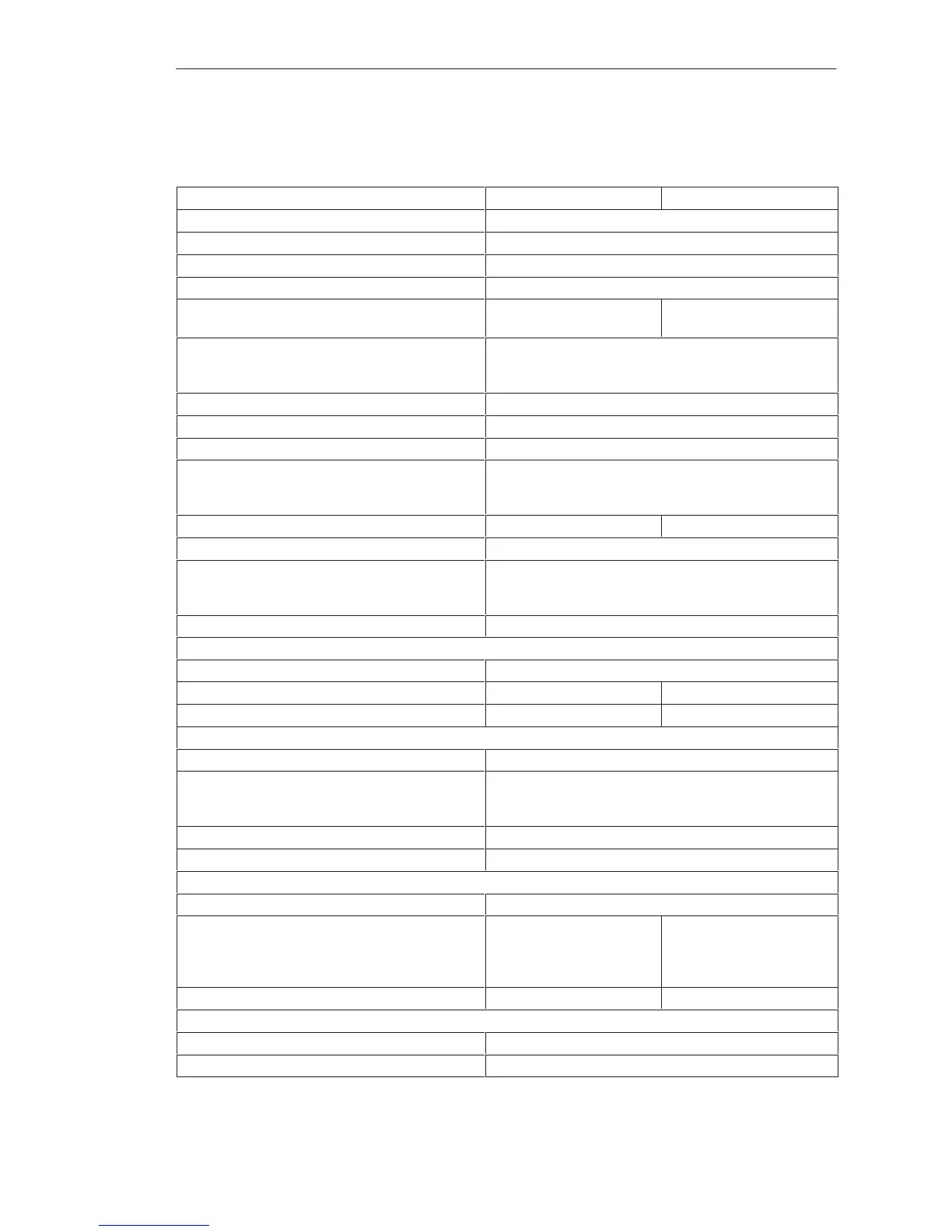
8.4.9 6ES5 441-4UA13/4UA14 Digital Output Module
–4UA13 –4UA14
Rated supply voltage L+ 24 V DC
Number of outputs 32, short-circuit protected
1)
Isolation no
Range for supply voltage 20 to 30 V DC
Fusing 6.3 A slow,
1 fuse per 8 outputs
7 A, fast, 1 fuse per 8 out-
puts
Output voltage
for logic 1
for logic 0
L+ -1.5 V min.
3 V max.
Switching current (resistive, inductive load) 5 mA to 0.5 A
Residual current at logic 0 0.5 mA max.
Switching current for lamps 0.22 A max. (5 W)
Switching frequency
with resistive load
with inductive load
100 Hz max.
2 Hz max. at 0.3 A, 0.5 Hz max. at 0.5 A
Breaking voltage (inductive) Limited to L+ – 47 V Limited to L+ –55 V
Total switching current 4 A max. per 8 outputs
Coincidence factor (total load capability)
ventilated
not ventilated
100 %
50 %; 100 % up to 35
o
C
Permissible line length 400 m max. unshielded
Power supply
Digital section from system bus 5 V, 80 mA typical
Current consumption from L+/L– 24 V, 150 mA typical 24 V, 200 mA typical
Power dissipation (rated operation) 17.0 W 6.4 W
Enable input (F+/F–)
Rated input voltage 24 V DC
Input voltage
for logic 1
for logic 0
13 to 33 V
– 33 to 5 V
Rated input current 5 mA
Permissible line length 200 m max.
Short-circuit monitoring
Indicator for signaling output (H+) Red LED for every 8 outputs
Output voltage
referred to L– (with feed at 1L+)
for logic 1
for logic 0
1L+ – 5 V min.
3 V max.
1L+ –1.5 V min.
3 V max.
Switching current 10 mA max., limited
Mechanical specifications
Dimensions (W x H x D) 20 mm x 255 mm x 195 mm
Weight Approx. 0.45 kg
1)
Short-circuit protection responds with line resistance v 15 ohms, irrelevant for the –4UA14 .
Di
ital Input/Output Modules
 Loading...

