3-36
System Manual
C79000-G8576-C199-06
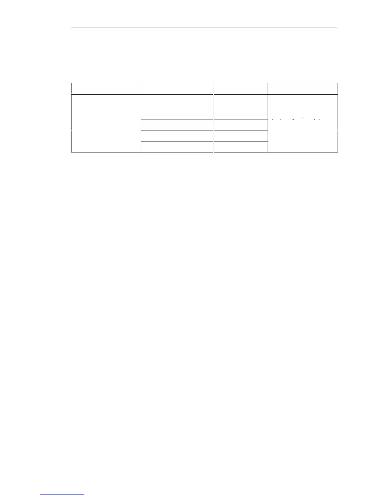
Where subracks (CC and EU) are arranged one above the other, the
installation clearances in the following table must be observed.
Upper Subrack Lower Subrack Min. Clearances Max. Clearances
S5-135U/ 155U
or
S5-115U
S5-135U 75 mm
87 mm if baffle
is used
The maximum clearance
is limited by the lengths
of connecting cables for
or
-
S5-115U with fan 60 mm
the interface modules.
-
S5-115U without fan 100 mm
S5-90U/ 95U/ 100U 75 mm
The following two points should be observed to improve the air circulation
within the cabinet:
The expansion unit with the greatest power dissipation to be removed
should be the upper unit.
If subracks of the S5-135U/155U series are installed together with
subracks of the S5-90U to 115U series in one cabinet, the rear panels of
all subracks must be at the same distance from the rear wall of the
cabinet.
Installation Guidelines
 Loading...

