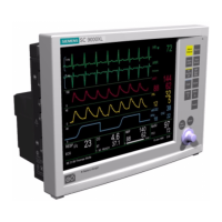
Service Manual SC 7000 and SC 9000XL Patient Monitors
86 Siemens Medical Systems, EM-PCS, Danvers ASK-T898-03-7600
NOT A CONTROLLED DOCUMENT
7k9kXLSM.c5.CD_ROM.fm/04-99/kaupp
NBP pump starts, but
cuff fails to inflate/
deflate properly
Cuff assembly
malfunction
NBP pneumatic system
malfunction
1. Recheck cuff assembly and installation, and replace
cuff assembly if defective.
2. If problem persists, remove rear cover and check
hose routing to cuff connector in NBP compartment
in rear housing.
3. If problem persists, open monitor and check that
pneumatic tubing to NBP transducer properly routed
and not obstructed.
4. Close monitor and perform characterization
procedure if tubing rerouted or obstruction removed
(see Section 4.7.4 on page 44 in Chapter 3).
5. If problem persists, replace NBP Subassembly.
6. If problem persists, contact TSS in Solna or Danvers.
NBP fails Interval
Mode or Safety Timer
Check
Main Processor PCB
Subassembly
malfunction
Software problem
1. Replace Main Processor PCB Subassembly.
2. If problem persists, contact TSS in Solna or Danvers
NBP fails hardware
overpressure check
Blockage between
pump manifold and cuff
connector
Main Processor PCB
malfunction
1. Power-cycle monitor to ensure that measurement
timout did not trigger premature pressure release,
and recheck.
2. If problem persists, remove rear cover and assure no
blockage in tubing between pump manifold and cuff
connector.
3. If problem persists, replace Main Processor PCB
Subassembly.
4. If problem persists, contact TSS in Solna or Danvers.
NBP parameter box
fails to appear when
cuff hose plugged into
NBP module
MAIN screen display
mode set for Manual
Cuff sensor defective or
not plugged into
Connector I/O PC
Board.
Main Processor PCB
malfunction
1. Assure
MAIN
screen display mode set to automatic.
2. If parameter box fails to appear, remove rear cover
and check that cuff sensor cable is plugged into X8
on Connector I/O PC Board.
3. • If sensor unplugged, plug sensor into X8 on
Connector I/O PC Board, and retest. If OK, return
monitor to clinical service.
• If sensor plugged in, unplug sensor and check for
continuity across pins of sensor cable connector.
— If continuity OK, (≈1.5Ω) replace Main
Processor PCB Subassembly.
— If continuity not OK, replace Rear Housing
Subassembly.
4. If problem persists, contact TSS in Solna or Danvers.
Table 5-9 NBP Malfunctions (Continued)
Symptom(s) Possible Cause(s) Troubleshooting and Remedial Action

 Loading...


