Service Manual SC 7000 and SC 9000XL Patient Monitors
102 Siemens Medical Systems, EM-PCS, Danvers ASK-T898-03-7600
NOT A CONTROLLED DOCUMENT
7k9kXLSM.apb.CD_ROM.fm/04-99/kaupp
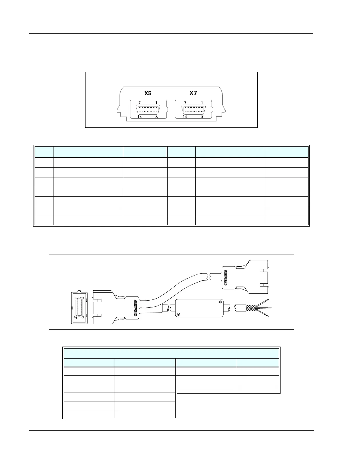
4 Interface Plate
Figure B-6)Interface Plate Connectors (Rear View (Refer to Table B-4.)
5 Recorder / Alarm Y Cable
Figure B-7Recorder / Alarm Y Cable (Accessory (Refer to Table B-5.))
Table B-4 Interface Plate Connectors Pinouts
Pin RECORDER/ALARM (X7) EXT CRT (X5) Pin RECORDER/ALARM (X7) EXT CRT (X5)
1 GND Ext Red 8 Rec CTS H Sync
2 +12VDC VGND 9 Alarm Out V Sync
3 Rec Tx Ext Grn 10 Rec GND Rem TxD
4 +12VDC VGND 11 Rec GND Rem RxD
5 Diag Tx Ext Blu 12 Rec Rx Power Switch
6 +12VDC VGND 13 Rec GND Rem Audio
7 Rec RTS GND 14 Diag Rx Rem Audio Ret
Table B-5 Recorder / Alarm Y Cable Connector Pinouts and Wire Color Code
Color Code (Alarm Cable)
Connector Pin No. Relay Input Wire Color SPDT Relay Output Circuit Status
1 TAN Brown RTN
2 NC Green Inactive Open
3 NC White Inactive Closed
4 - 8 NC
9 ORANGE
10 - 14 NC
;
;

 Loading...


