Service Manual SC 7000 and SC 9000XL Patient Monitors
106 Siemens Medical Systems, EM-PCS, Danvers ASK-T898-03-7600
NOT A CONTROLLED DOCUMENT
7k9kXLSM.apb.CD_ROM.fm/04-99/kaupp
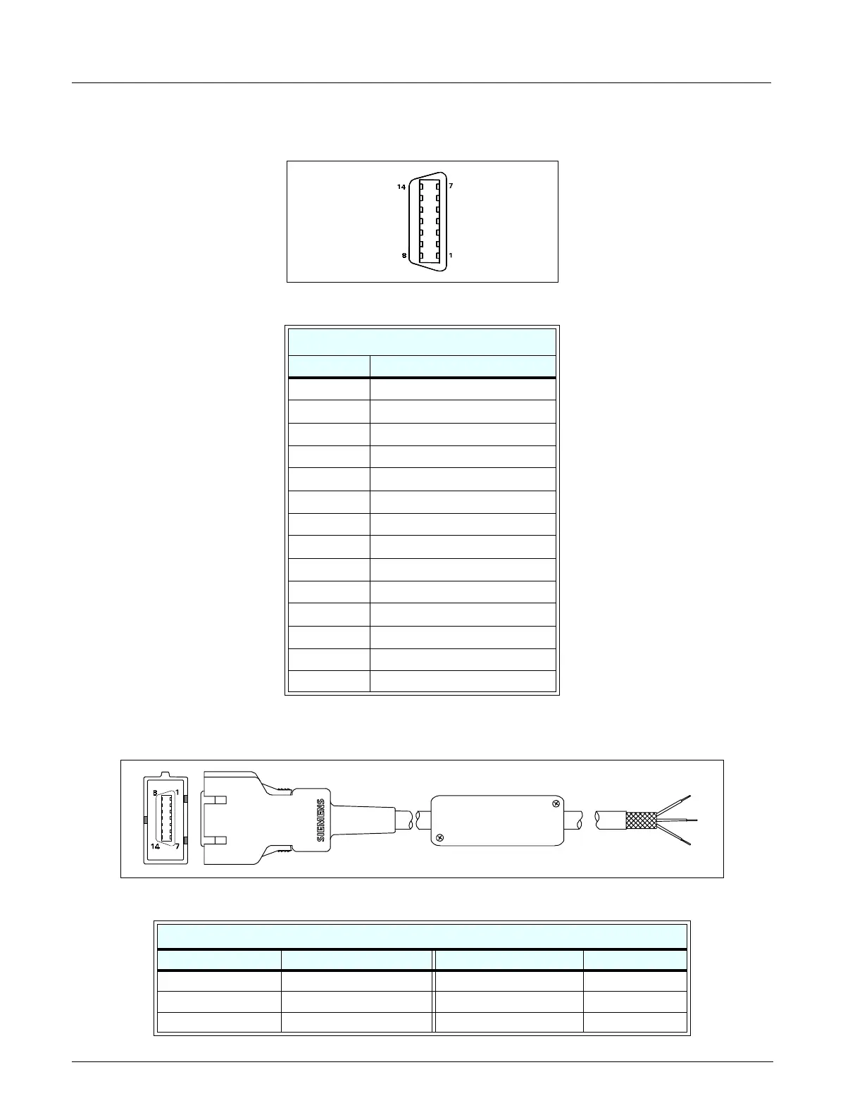
11SC 7000 / SC 9000XL RS-232, Keypad Input, Alarm Out Connector, X8
Figure B-14 RS-232, Keypad Input, Alarm Out Connector (see Table B-12)
12Remote Alarm Cable
Figure B-15Remote Alarm Cable - Unterminated (Refer toTable B-13)
Table B-12 RS-232, Keypad Input, Alarm Out Connector Pinouts
RS-232, Keypad Input, Alarm Out
Pin No. Signal
1GND
2COM 1 TXD
3 REM PWR
4 MC800TL
5COM2 TXD
6SER. D OUT
7SER. FSL
8COM 1 RXD
9ALRM OUT L
10 GND
11 COM2 RXD
12 SER. D IN
13 SER. CLK
14 GND
Table B-13 Remote Alarm Cable Connector Pinouts and Wire Color Code
Color Code
Connector Pin No. Relay Input Wire Color SPDT Relay Output Circuit Status
1 TAN Brown RTN
2 - 8, 10 - 14 NC Green Inactive Open
9 ORANGE White Inactive Closed

 Loading...


