SC 7000 and SC 9000XL Patient Monitors Service Manual
ASK-T898-03-7600 Siemens Medical Systems, EM-PCS Danvers 89
7k9kXLSM.c5.CD_ROM.fm/04-99/kaupp
NOT A CONTROLLED DOCUMENT
15No Printout from Recorder.
Table 5-12 Recorder Problems
Symptoms Possible Cause(s) Troubleshooting and Remedial Action
Recorder Power LED
NOT illuminated
Recorder malfunction
Cabling malfunction
Interface Plate (if
installed) malfunction
CPS / IDS (if installed)
malfunction
Main Processor PCB
malfunction
1. Assure that all units in the power chain are properly
connected and powered ON.
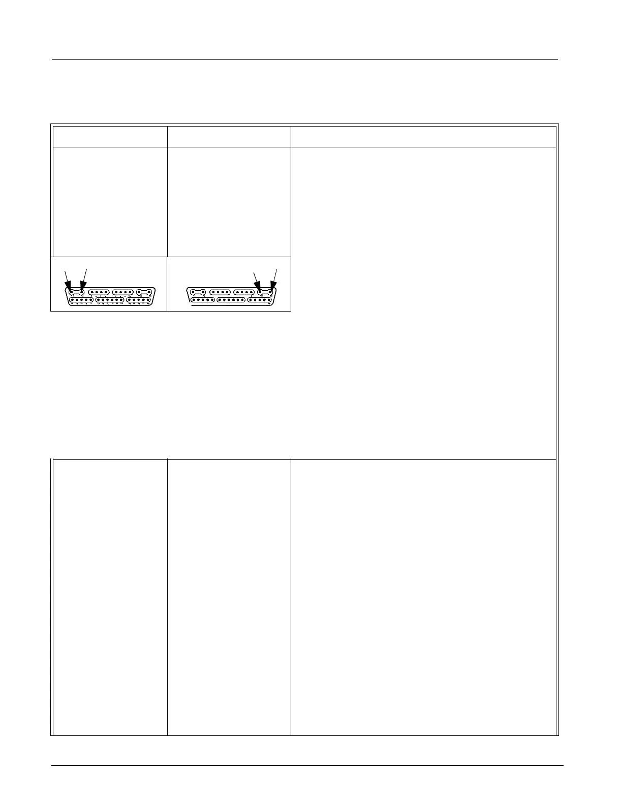
2. If problem persists do either a or b. Refer to
illustrations below left.
a If Recorder has installed Interface Plate, detach
Interface Plate from Recorder and check voltage
between pins 1 and 2 on Interface Plate docking
connector.
b If Recorder mounted on Auxiliary Docking Station,
check voltage between pins 1 and 2 on Auxiliary
Docking Station connector.
3. If voltage O.K., replace Recorder. (With newer SW
versions voltage may pulse. This is normal.)
4. If voltage NOT O.K., check for +12VDC between pins
1 and 2 on monitor docking connector.
5. • If voltage O.K., check for +12VDC between pins 1
and 2 of all docking connectors in path between
monitor and recorder, and between pins 2 and 15
of X13 on CPS or IDS. Replace component that
fails to provide 12VDC at the appropriate pins.
• If voltage not O.K. on monitor docking connector,
replace Main Processor PCB Subassembly.
Local Recorder
connected directly to
Monitor in standalone
configuration
Recorder power LED
illuminated
Recorder malfunction
Interconnecting cable or
connection malfunction
Recorder or Monitor
Interface Plate
malfunction
Main Processor PCB
malfunction
1. With an ECG waveform from patient simulator on
Monitor display, press Record key.
2. • If “Recorder Not Connected” message appears in
the message field, continue to step 3.
• Press Zoom key and select Event Recall. After ≈20
sec, BED TIMED strip should appear on display. If
BED TIMED strip fails to appear, replace Front
Bezel Subassembly and go to step 6. Otherwise,
continue to step 4.
3. If problem persists, and Recorder Cable Art. No.
4318130E530U is installed, replace Recorder cable
and go to step 5.
4. If separate Interface Plates and Recorder cable are
installed, replace each item one at a time to isolate
possible malfunction.
5. If problem persists, replace Recorder.
6. If problem persists, replace Main Processor PCB
Subassembly.
7. If problem persists, contact TSS in Solna or Danvers.
Monitor Docking Connector
Interface Plate, Auxiliary
Docking Connector
Docking Station -
12
1
2

 Loading...


