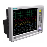
SC 7000 and SC 9000XL Patient Monitors Service Manual
ASK-T898-03-7600 Siemens Medical Systems, EM-PCS Danvers 45
7k9kXLSM.c3.CD_ROM.fm/04-99/kaupp NOT A CONTROLLED DOCUMENT
5) With monitor in Adult mode, power monitor ON and set following in
NBP parameter field menu:
• Interval Time - OFF
• Continuous Mode - OFF
• Calibrate Mode - ON. (Observe “NBP Cal. = 0 mmHg” appears.)
6) Perform a calibration check. Refer to Section 10.2 on page 65 in
Chapter 4.
4.7.5 NBP Characterization Note: Always perform NBP calibration check before attempting
characterization. Perform NBP calibration if NBP fails calibration
check.
1) Disconnect calibration assembly hose from canister, and using adult
hose, connect .5l pressure canister directly to monitor cuff connector.
2) Press Main Menu key, and select Monitor Setup → Biomed → Service.
3) Enter service password (4712) and select Accept.
4) Select Characterization → NBP Char.
5) Verify that “NBP Characterizing” displays in message field. When
message blanks, process has completed.
Note: (If characterization fails, refer to Section 12.2, “NBP
Troubleshooting” in Chapter 5.)
6) Press Main Screen key.
7) Functionally verify proper operation of monitor’s NBP function.
4.8 Replacing Monitor
Handle
1) Remove left and right side panels from monitor. See Section 5.1.
2) Remove and save securing screws (
A
in Figure 3-2 on page 40), and
extract handle through top of monitor.
3) Install new handle through top of monitor, reinstall securing screws,
and reinstall left and right side panels.
5 Opening Monitor
Before attempting to open the monitor, always do the following:
• Remove all attached modules and unplug all cables from the monitor.
• Disconnect all external power sources, remove external battery (if
installed), and remove back cover and unplug cable from main battery.
• Assure that both you and the work area are properly protected against
static-electricity discharge.
5.1 Removing/Installing
Side-Panels
The first step in opening the monitor is to remove the left and right side
panels, which are each secured to the monitor housing with several locking
tabs and two pressure-sensitive latches. Remove the panels as follows:
Note: Before the right-hand panel can be removed, it is necessary to
remove the cover from the PCMCIA card ejector shaft.
5.1.1 Removing Ejection Shaft
Cover
1) Insert PCMCIA card into memory card slot on right-hand side of
monitor to force ejector button out.
2) Remove and save ejector shaft cover. To remove cover, grasp front
and back sides of cover between your thumb and forefinger, squeeze
cover slightly, and
carefully
rock cover off of shaft in direction of arrow
shown at top left of next page.

 Loading...


