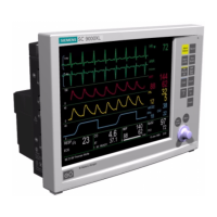
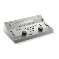
SC 7000 and SC 9000XL Patient Monitors Service Manual
ASK-T898-03-7600 Siemens Medical Systems, EM-PCS Danvers 39
7k9kXLSM.c3.CD_ROM.fm/04-99/kaupp NOT A CONTROLLED DOCUMENT
4.2.1 Removing Existing Label To remove existing label, carefully peel up one corner of label and pull it
towards opposite corner.
Caution
Use extreme care to not damage underlying membrane keypad
when replacing Language Label. If membrane keypad is damaged
the Front Bezel/Lens Subassembly must be replaced.
4.2.2 Installing Language Label 1) Peel protective covering from section of new label under function keys.
2) Position label on membrane keypad so that it fits squarely in label
depression allowance on front bezel, and using a sweeping or rolling
motion to prevent air bubbles from becoming trapped under label,
press on label to secure it to membrane keypad.
3) Remove protective covering from remainder of language label, and
with a similar motion affix label along bottom of bezel.
4.2.3 Installing SIEMENS Metal
Logo Label
Use this procedure if SIEMENS metal logo label not already installed on
front bezel.
1) Peel protective covering from new label.
2) Position in left rectangular depression in area near top left corner of
front bezel.
3) Press firmly, using a sweeping motion to prevent air bubbles from
becoming trapped under label.
4.2.4 Installing Monitor Model
Label
1) Peel protective covering from appropriate new monitor model label.
Discard other new label.
2) Position NEW label in rectangular depression to right of SIEMENS
metal logo label in area near top left corner of front bezel.
3) Press firmly, using a sweeping motion to prevent air bubbles from
becoming trapped under label.
4.3 Replacing Foot Pads
Two feet are on the bottom of the front bezel subassembly (see
3
in Figure
3-10 on page 51, and four are on the bottom of the rear housing (see
7
in
Figure 3-2 on page 40). Pads are secured in foot wells by adhesive.
1) Remove all remnants of existing pad and adhesive from foot well.
2) Remove protective covering from adhesive surface of replacement pad.
3) Position replacement pad in foot well, and press firmly on pad to
secure it in well.
4.4 Removing / Installing
External Battery and
Support Components
The external battery (
7
in Figure 3-1) and main battery (
0
in Figures 3-1
and 3-2) are contained in compartments on the rear of the monitor. It is
necessary to remove the back cover
6
only to replace the main battery.
4.4.1 External Battery (optional) The external battery compartment door is hinged to the compartment
housing on the right-hand end (facing the back of the monitor). The door
(
8
in Figure 3-2) has been designed to lift the battery as an assist to the
ejection spring (
@
in Figure 3-2) at the opposite end of the compartment
when the battery is being removed. It also secures the battery in the
compartment and assures good electrical connection to the battery
connector when closed.

 Loading...


