Service Manual SC 7000 and SC 9000XL Patient Monitors
42 Siemens Medical Systems, EM-PCS, Danvers ASK-T898-03-7600
NOT A CONTROLLED DOCUMENT 7k9kXLSM.c3.CD_ROM.fm/04-99/kaupp
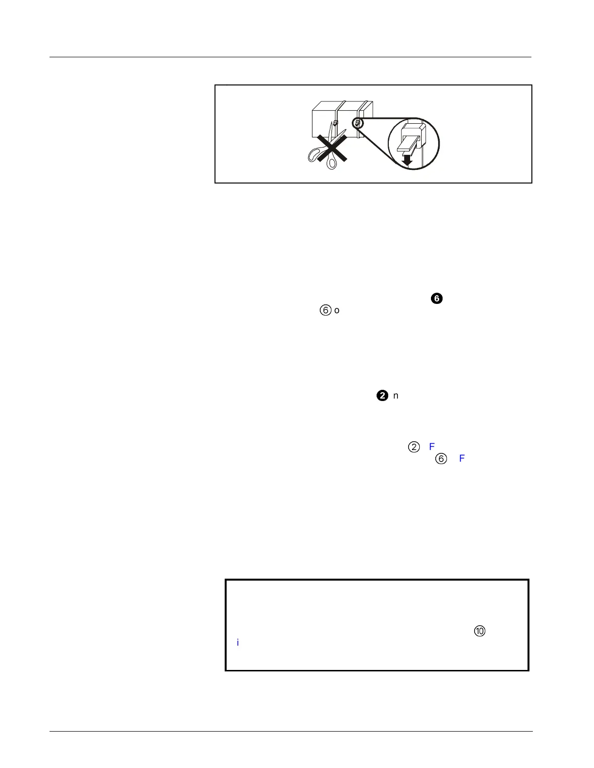
Figure 3-3 Battery Cable Ties
3) Depress release tab on each ty-wrap lock (see Figure 3-3) and pull ty-
wrap tongues out of locks to free battery.
4) Note routing of speaker cable, and slide battery out of compartment.
Installing Main Battery Reverse steps of removal procedure to install main battery. Route speaker
cable as noted in step 4 above before resecuring ty-wrap on main battery.
4.6 Replacing Power
Cable and Speaker
Subassembly
1) Remove external battery (if installed).
2) Remove and save three Phillips-head screws (
=
in Figure 3-2)
securing back cover
6
on back of monitor, and remove cover.
3) Using long nose pliers, unplug battery connectors from main battery.
Be careful to NOT damage in-line fuse (if installed). Note polarity
of battery cable wires!
Red goes to +; Black goes to -.
4) Slide external battery connector out of channel in battery
compartment.
Note: Do not remove ferrite filter (
H
in Figure 3-2) from cable
subassembly. Note positioning of filter in connector compartment, and
locate in same position when installing new cable subassembly.
5) Using long-nose pliers, unplug speaker connector from X7 (see Figure 3-
1 on page 40) and power cable connector (
@
inFigure 3-1 and in Figure
3-2) from Connector I/O PCB in connector cavity (
6
in Figure 3-1), and
remove power cable subassembly.
6) Depress release tab on each ty-wrap lock (see Figure 3-3) and pull ty-
wrap tongues out of locks to permit removal of speaker cable. Note
routing of speaker cable for use in reassembly.
7) Slide speaker out of slots in rear housing, and remove power cable
and speaker subassembly.
8) Reverse procedure of steps 1 through 5 to install replacement power
cable and speaker subassembly.
Caution
Sandwich wires of power cable and speaker subassembly
between left side of housing and flat plastic cable guide (
in
Figure 3-1 on page 40) to prevent possible damage to harness when
installing rear housing screws.

 Loading...


