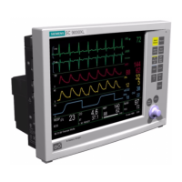
Service Manual SC 7000 and SC 9000XL Patient Monitors
xii Siemens Medical Systems, EM-PCS, Danvers ASK-T898-03-7600
NOT A CONTROLLED DOCUMENT
7k9kXLSM.book.CD_ROMTOC.fm/04-99/kaupp
12Remote Alarm Cable . . . . . . . . . . . . . . . . . . . . . . . . . . . . . . . . . . . . . . . . . . . . . . . . . . . . . . 106
Figure B-15 Remote Alarm Cable - Unterminated (Refer toTable B-13) . . . . . . . . . . . . . 106
Table B-13Remote Alarm Cable Connector Pinouts and Wire Color Code . . . . . . . 106
13Analog Cable . . . . . . . . . . . . . . . . . . . . . . . . . . . . . . . . . . . . . . . . . . . . . . . . . . . . . . . . . . . . 107
Figure B-16 Analog Cable (Unterminated - Refer to Table B-14.) . . . . . . . . . . . . . . . . . . 107
Table B-14Analog Cable Color Code . . . . . . . . . . . . . . . . . . . . . . . . . . . . . . . . . . . . . . 107
14PSL Connector . . . . . . . . . . . . . . . . . . . . . . . . . . . . . . . . . . . . . . . . . . . . . . . . . . . . . . . . . . . 107
Figure B-17 PSL Connector (Refer to Table B-15.) . . . . . . . . . . . . . . . . . . . . . . . . . . . . . 107
Table B-15PSL Connector Pins . . . . . . . . . . . . . . . . . . . . . . . . . . . . . . . . . . . . . . . . . . 107
15Cardiac Output Intermediate Cable Wiring Diagram . . . . . . . . . . . . . . . . . . . . . . . . . . . . 108
Figure B-18 Cardiac Output Intermediate Cable Wiring Diagram . . . . . . . . . . . . . . . . . 108
16Input Connector on etCO2 Module . . . . . . . . . . . . . . . . . . . . . . . . . . . . . . . . . . . . . . . . . . . 109
Figure B-19 Input Connector on etCO2 Module (Refer to Table B-16.) . . . . . . . . . . . . . 109
Table B-16etCO2 Module Input Connector Pins . . . . . . . . . . . . . . . . . . . . . . . . . . . . 109
17SC 9015 Remote Display . . . . . . . . . . . . . . . . . . . . . . . . . . . . . . . . . . . . . . . . . . . . . . . . . . . 110
Figure B-20 SC 9015 Remote Display - Rear View (Refer to Table B-17.) . . . . . . . . . . . 110
Table B-17SC9015 Remote Display Connector Pins . . . . . . . . . . . . . . . . . . . . . . . . . 110
18HEMO Pod . . . . . . . . . . . . . . . . . . . . . . . . . . . . . . . . . . . . . . . . . . . . . . . . . . . . . . . . . . . . . . . 111
Figure B-21 HEMO Pod Connectors (Refer to Table B-18.) . . . . . . . . . . . . . . . . . . . . . . 111
Figure B-22 Press Adapter Input (Refer to Table B-19.) . . . . . . . . . . . . . . . . . . . . . . . . . 111
Table B-18HEMO Pod Connector Signals . . . . . . . . . . . . . . . . . . . . . . . . . . . . . . . . . . 111
Table B-19PRESS Input Connector . . . . . . . . . . . . . . . . . . . . . . . . . . . . . . . . . . . . . . . 111
Appendix C: Diagnostic/Error Messages . . . . . . . . . . . . . . . . . . . . . . . . . . . . . . . . . . . .113
1 Overview of Diagnostic Messages . . . . . . . . . . . . . . . . . . . . . . . . . . . . . . . . . . . . . . . . . . . 113
Table C-1Diagnostic Log Codes . . . . . . . . . . . . . . . . . . . . . . . . . . . . . . . . . . . . . . . . . 113
Appendix D: Functional Verification Checklist . . . . . . . . . . . . . . . . . . . . . . . . . . . . . . .135
Clinical Site Report . . . . . . . . . . . . . . . . . . . . . . . . . . . . . . . . . . . . . . . . . . . . . . . . .138
Appendix E: Service Setup Instructions . . . . . . . . . . . . . . . . . . . . . . . . . . . . . . . . . . . . .139

 Loading...


