Installation
5.2 Installing a switch
SCALANCE X-300
104 Operating Instructions, 10/2010, A5E01113043-10
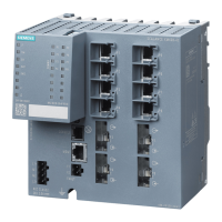
Standard position
Normal orientation of the device
The ventilation grilles are on the top, bottom and sides of the
housing.
The LED display is on the left of the front panel of the
housing.
To the right of the LED display, the SCALANCE XR-300 has
connectors for the signaling contacts and the power supply.
Note that the SCALANCE XR-300 is available for different
power supplies (100 to 240 V AC and 24 V DC variants).
The Ethernet ports or the slots for the modules are also on
the front of the housing. Slots for the modules are fitted with
dummy covers.
The C-PLUG is on the right behind a protective panel
secured with screws.
(For more detailed information, refer to the section on the C-
PLUG in the X-300 operating instructions.)
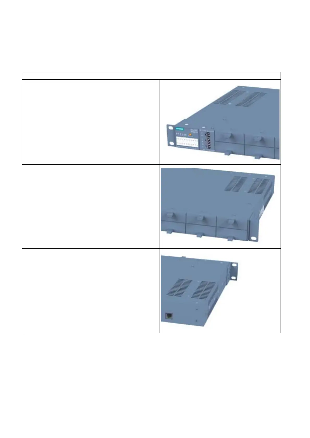
On the back of the housing, you will find the diagnostics port
of the device. (For more details, refer to Diagnostics port
XR-300.) On the SCALANCE X-300M EEC, you will also
find the connectors for the signaling contacts and power
supply here.

 Loading...