3-19© Siemens AG 2007 All Rights Reserved
SICLOCK
®
TC 400
Hardware Description 3
This chapter describes the hardware design with connections, the operator con-
trols and displays.
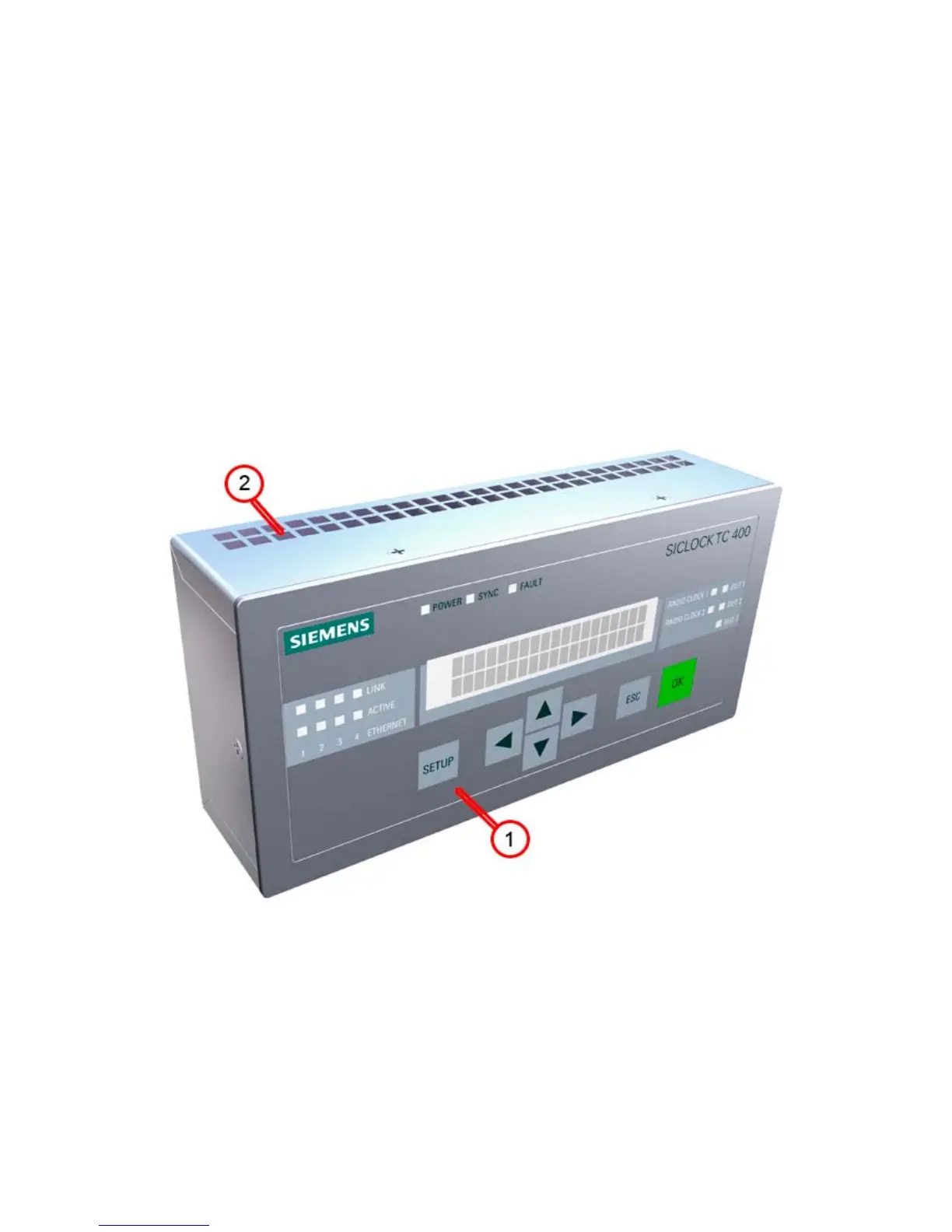
3.1 External design
The following figures show the displays and operator controls as well as the con-
nections of the SICLOCK TC 400.
Figure 3-1 SICLOCK TC 400 - perspective view with front panel and ventilation grille
(1) Panel with operator controls and displays
(2) Ventilation grille
 Loading...