6-33© Siemens AG 2007 All Rights Reserved
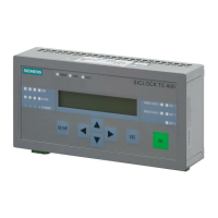
SICLOCK
®
TC 400
Connecting 6
6.1 Connecting overview
Note the following requirements for the setup:
• The device may only be connected to 24 VDC power supplies that meet the
requirements of a functional extra-low-voltage with safe isolation (PELV). The
cable cross-section must be chosen to ensure that no damage can result from
a cable overheating in the event of a short-circuit in the SICLOCK TC 400. For
cable cross-section, see Connecting the power supply (Section 6.2).
• Avoid extreme environmental conditions as far as possible.
• Protect the device against dust, moisture, heat and severe vibration.
• Do not place the device in direct sunlight.
• Install the device in such a way that it does not present a hazard (e.g. by falling
out).
• Do not cover the vent slots.
• Permitted mounting position (Section 4.4.2).
Caution
Only connect I/O devices that are suitable for industrial use.
Caution
Strictly adhere to the specifications for I/O devices.
 Loading...