Connecting
6-39
© Siemens AG 2007 All Rights Reserved
SICLOCK
®
TC 400
6.3.3 SICLOCK GPSDEC
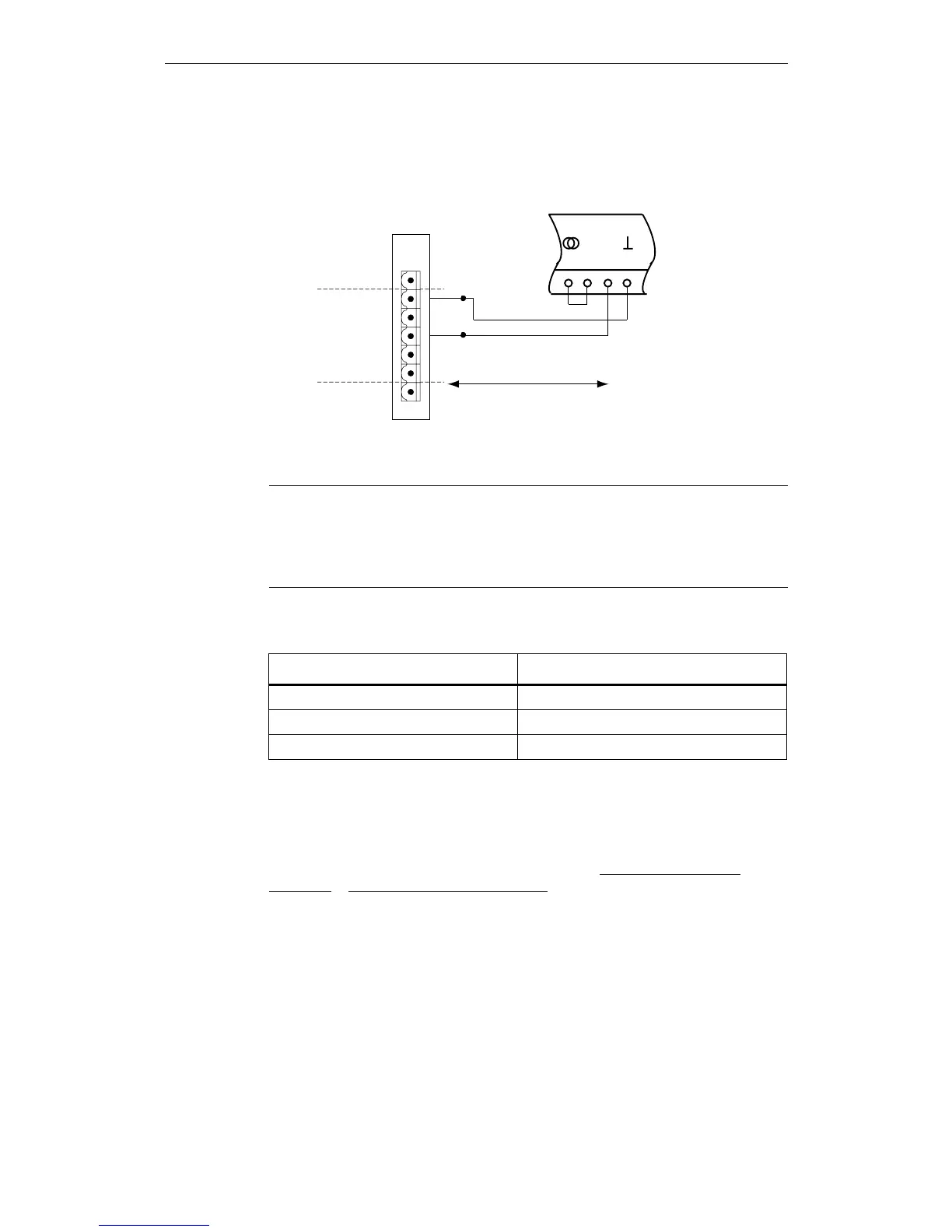
A SICLOCK GPSDEC decoder is connected as shown in Fig. 6-5.
Figure 6-5 SICLOCK GPSDEC radio clock connection to RADIO CLOCK 1
Functional check
When the GPSDEC is receiving correctly, the "RADIO CLOCK 1" or "RADIO
CLOCK 2" LED on the front panel should flash at approx. 1 Hz.
After receiving for approximately three minutes the /Inputs/Input 1/Status
(0.20.02) or /Inputs/Input 2/Status (0.21.02) parameter must change to "GPS" or
"DCF77".
Caution
The SICLOCK GPSDEC may only be operated as active radio clock.
Operation as passive radio clock results in the destruction of the SICLOCK GPS-
DEC.
Table 6-2 Recommended parameterization of the GPSDEC decoder for the
SICLOCK TC 400 synchronization
Parameter Setting
Time difference compared to GMT 00:00
Switchover to daylight saving time "None"
X1.5-8 (DCF77TTY) "DCF without ZZB"
PD[P
'&)77<
5$',2&/2&.*1'
5$',2&/2&.$
5$',2&/2&.%
5$',2&/2&.$
5$',2&/2&.%
6
7
8
9
10
11
;
 Loading...