5-31© Siemens AG 2007 All Rights Reserved
SICLOCK
®
TC 400
Installation 5
5.1 Installation overview
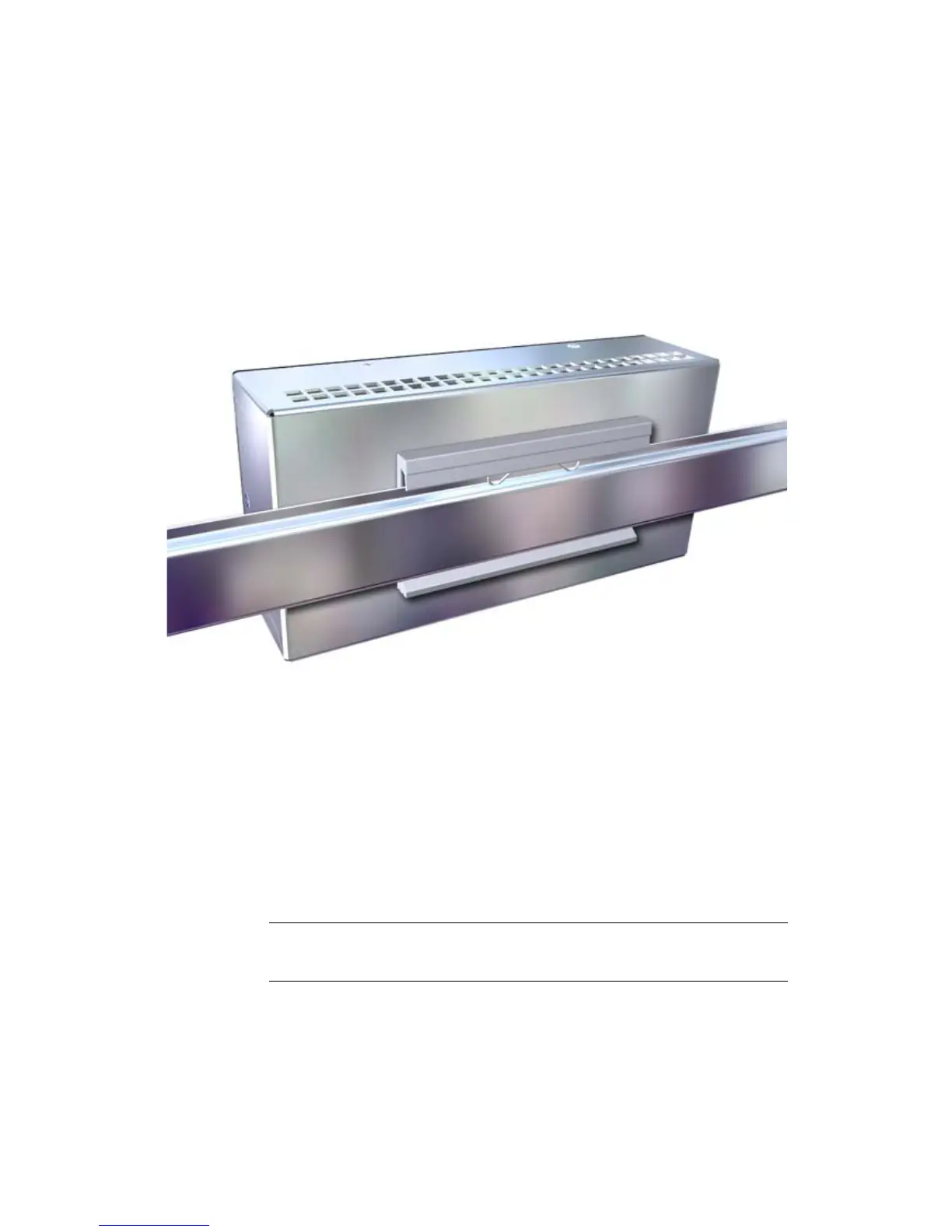
Figure 5-1 SICLOCK TC 400 - installation view
The SICLOCK TC 400 should be installed in the control cabinet at an easily
accessible position.
The housing can be snapped onto DIN rails (EN 50022-35) or fixed to SIMATIC
S5 standard mounting rails (6ES5 710-8maxx).
There must be a space of 100 mm above the device for snapping the device on
and off the DIN rail and for unobstructed heat dissipation.
There must be a space of at least 100 mm below the device for the process signal
connectors.
It is recommended that a suitable cable duct be installed below this space.
See also Dimension Drawing (Section 14).
Note
Ensure that the snap fasteners are correctly locked.
 Loading...