Connecting
6-38
© Siemens AG 2007 All Rights Reserved
SICLOCK
®
TC 400
6.3.2 SICLOCK DCFRS industrial version
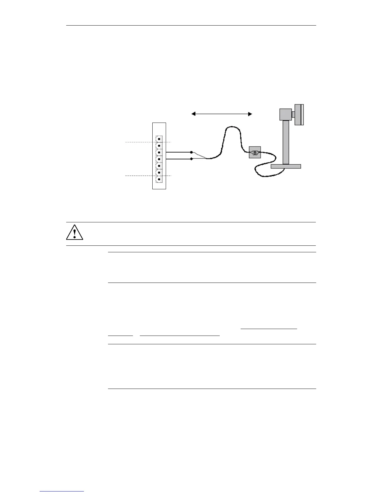
The industrial version of the SICLOCK DCFRS radio clock contained in the
DCF77 package is connected as shown in Fig. 6-4. The polarity is not important
here.
Figure 6-4 SICLOCK DCFRS industrial version radio clock connection to
RADIO CLOCK 1
Functional check
When the SICLOCK DCFRS is receiving correctly, the "RADIO CLOCK 1" or
"RADIO CLOCK 2" LED on the front panel should flash at approx. 1 Hz.
After receiving for approximately three minutes the /Inputs/Input 1/Status
(0.20.02) or /Inputs/Input 2/Status (0.21.02) parameter must change to "DCF77".
5$',2&/2&.*1'
5$',2&/2&.$
5$',2&/2&.%
5$',2&/2&.$
5$',2&/2&.%
6
7
8
9
10
11
;
max. 1000 m
Warning
Lightning protection must also be installed when used outdoors.
Note
The radio clock cable shield should be connected one-sided to a suitable place at
the installation location.
Note
When selecting the location for the antenna, it is especially important that there is
as little electromagnetic interference on the DCF77 carrier frequency as possible.
Do not mount the antenna close to drives, neon lamps, monitors and other emit-
ters of interference.
 Loading...