Connecting
6-35
© Siemens AG 2007 All Rights Reserved
SICLOCK
®
TC 400
6.3 Connecting the external synchronization
The signal of the connected radio clock is detected automatically and displayed
in the /Inputs/Input 1/Status (0.20.02)
parameter (or /Inputs/Input 2/Status
(0.21.02) parameter).
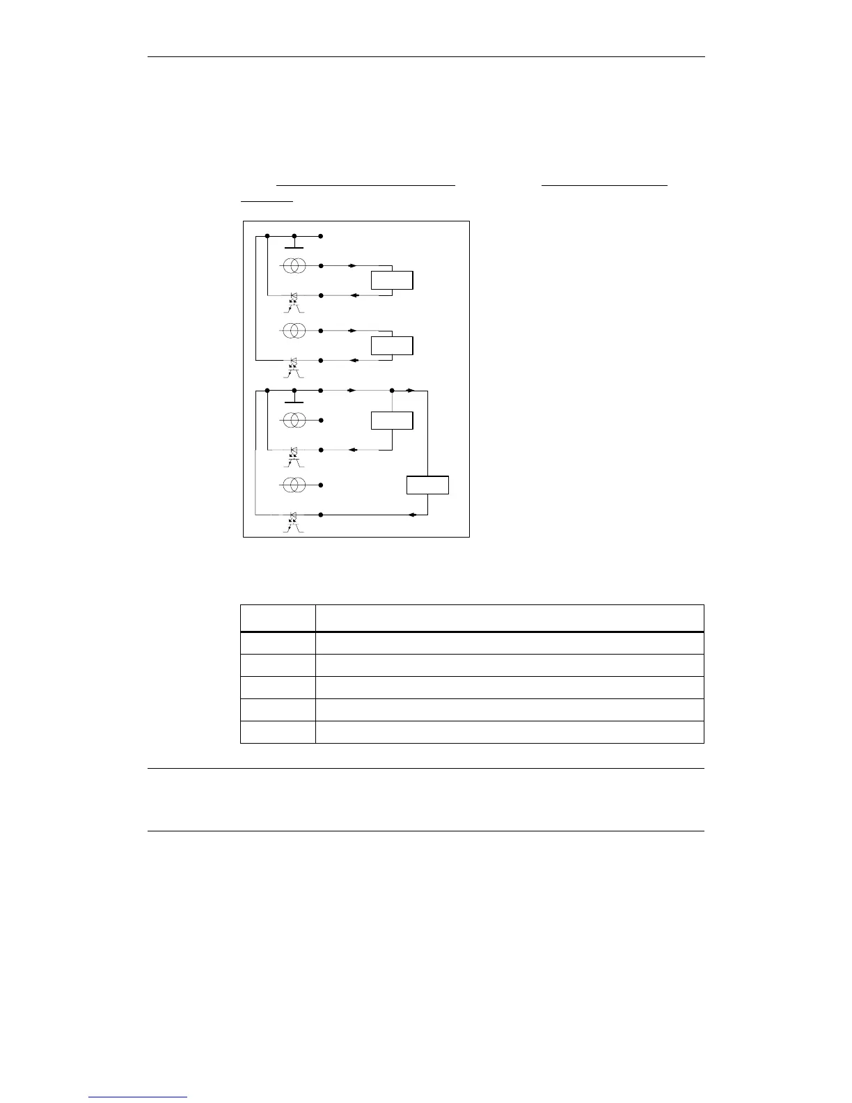
Figure 6-2 Circuit diagram for a passive and an active radio clock
Table 6-1 Terminal assignment of the radio clock inputs
Terminal Designation
X2-7 RADIO CLOCK GND
X2-8 RADIO CLOCK 1A
X2-9 RADIO CLOCK 1B
X2-10 RADIO CLOCK 2A
X2-11 RADIO CLOCK 2B
X2-8
X2-9
48 V
X2-7
passive
Radio Clock 1
X2-8
X2-9
48 V
X2-7
active
Radio Clock 1
passive
Radio Clock 2
X2-10
X2-11
48 V
X2-10
X2-11
48 V
active
Radio Clock 2
Note
If you are operating two radio clocks, connect the preferred model to RADIO
CLOCK 1.
 Loading...