Connecting
6-37
© Siemens AG 2007 All Rights Reserved
SICLOCK
®
TC 400
6.3.1 SICLOCK GPS1000
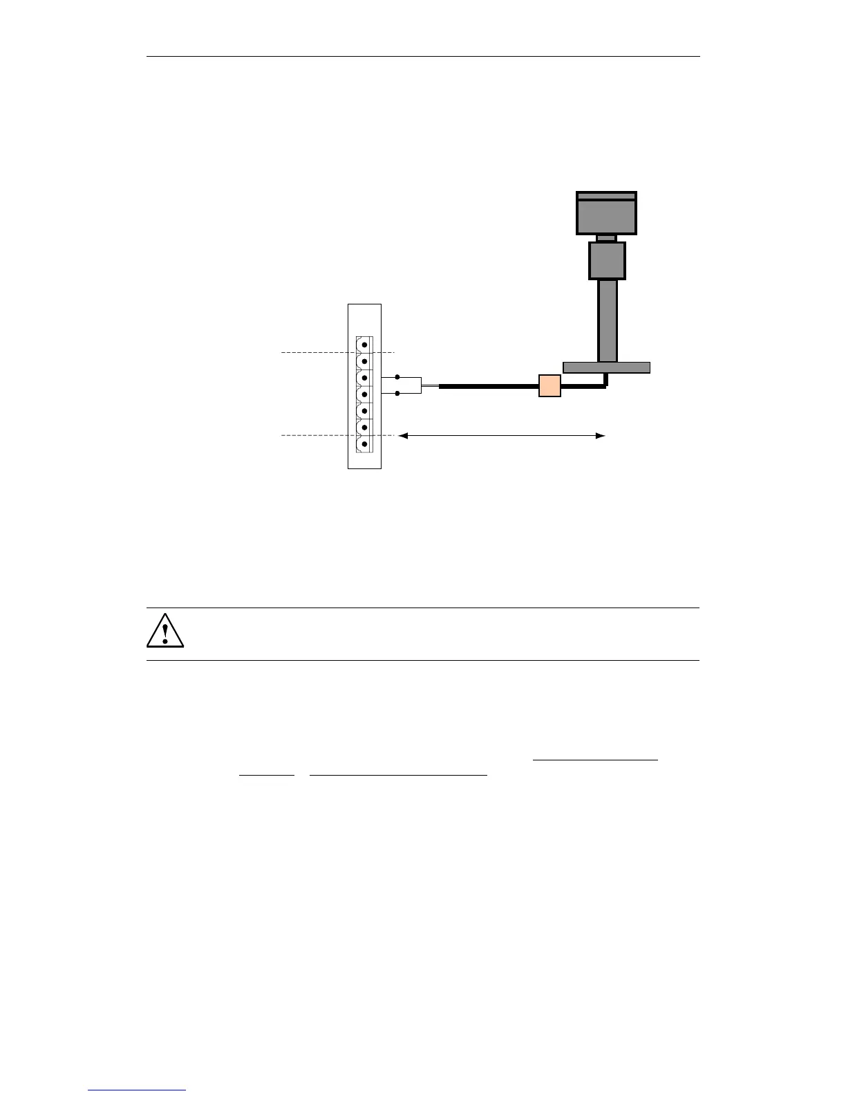
The GPS1000 receiver is connected as shown in Fig. 6-3.
Figure 6-3 SICLOCK GPS1000 radio clock connection to RADIO CLOCK 1
We recommend a 2-wire, shielded cable, e.g. LiYCY 2x1 mm², as radio clock
cable. The cable shield should be connected one-sided to a suitable place at the
installation location.
An additional parameterization of the GPS1000 is not required.
Functional check
When the GPS1000 is receiving correctly, the "RADIO CLOCK 1" or "RADIO
CLOCK 2" LED on the front panel should flash at approx. 1 Hz.
After receiving for approximately three minutes the /Inputs/Input 1/Status
(0.20.02) or /Inputs/Input 2/Status (0.21.02) parameter must change to "GPS".
/LJKWQLQJSURWHFWLRQ
PD[P
5$',2&/2&.*1'
5$',2&/2&.$
5$',2&/2&.%
5$',2&/2&.$
5$',2&/2&.%
6
7
8
9
10
11
;
Warning
Use lightning protection for the outdoor GPS antenna.
 Loading...