Hardware Description
3-20
© Siemens AG 2007 All Rights Reserved
SICLOCK
®
TC 400
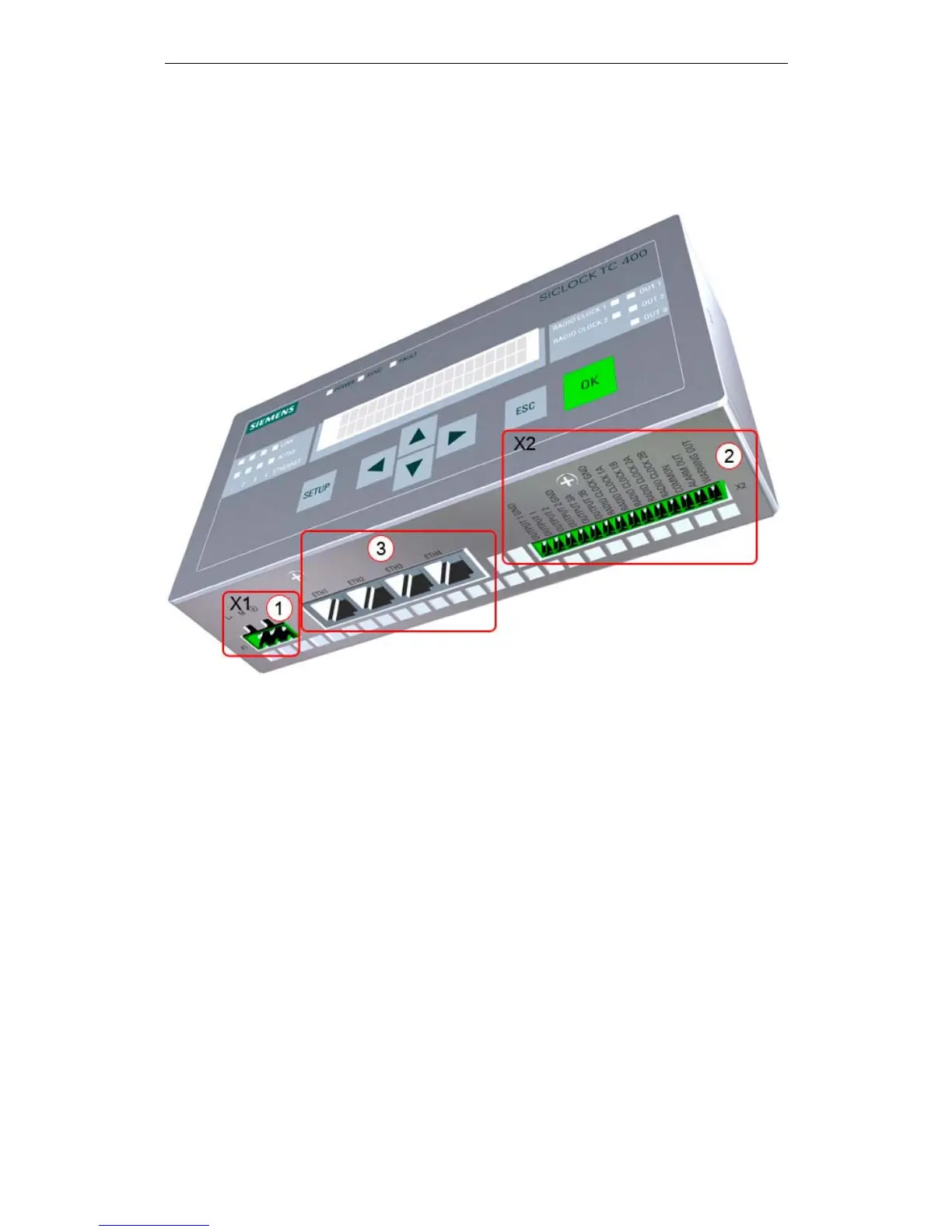
3.2 Connection elements
The following figure shows the connections of the SICLOCK TC 400.
Figure 3-2 SICLOCK TC 400 - arrangement of the connections
(1) Terminal X1 - 24 V power supply
(2) Terminal X2 - connecting terminal for radio clocks, outputs and alarm
See also Terminal assignment (Section 15.1).
(3) Four Ethernet ports
 Loading...