Connecting
6-44
© Siemens AG 2007 All Rights Reserved
SICLOCK
®
TC 400
6.5 Connecting an alarm output and a warning output
The SICLOCK TC 400 automatically performs various functional tests during
operation. When an error occurs, the appropriate messages are generated on the
display. A distinction is made between alarms and warnings.
An alarm output and a warning output are available on terminal X2 for the external
monitoring.
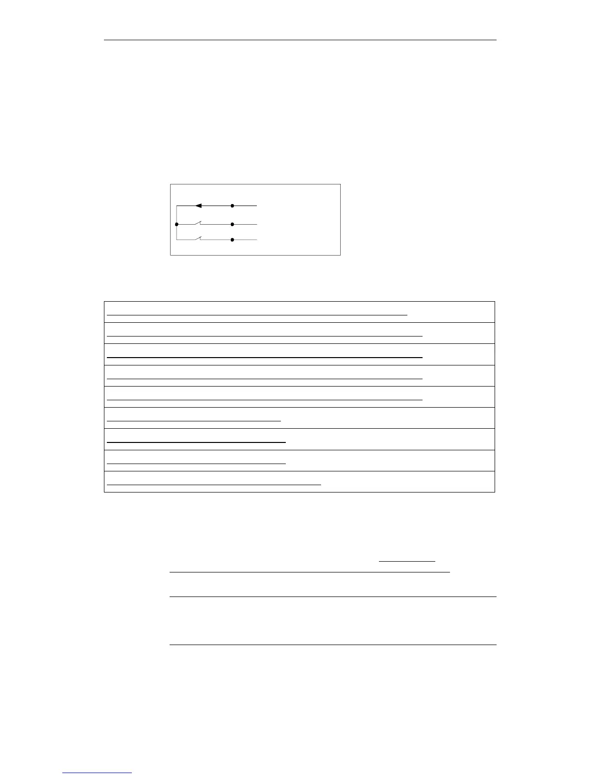
Figure 6-9 Alarm output X2-13 and warning output X2-14
Example:
The alarm output is to be set when no external synchronization is available.
With the configuration tool, set the parameter entry /Synchroniza-
tion/Advanced/Monitoring/monitor status of synchronization (0.09.14) = "Alarm"
to activate the monitoring / alarm output when an error occurs.
;
;
;
Table 6-5 Parameters that influence the alarm response
/Synchronization/Advanced/Monitoring/monitor status of synchronization (0.09.14)
/Network Settings/Ethernet 1/Advanced Settings Adapter 1/monitor link state (0.05.09)
/Network Settings/Ethernet 2/Advanced Settings Adapter 2/monitor link state (0.05.10)
/Network Settings/Ethernet 3/Advanced Settings Adapter 3/monitor link state (0.05.11)
/Network Settings/Ethernet 4/Advanced Settings Adapter 1/monitor link state (0.05.12)
/NTP Client/Monitoring/monitor server (0.18.04)
/Inputs/Input 1/Monitoring/monitor input (0.20.01)
/Inputs/Input 2/Monitoring/monitor input (0.21.01)
/Environment/Advanced/Temperature/monitoring (0.24.01)
Note
The contacts are designed as fail-safe NC contacts. The appropriate contact is
opened when an alarm or a warning is pending.
 Loading...