Hardware Description
3-22
© Siemens AG 2007 All Rights Reserved
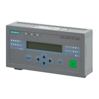
SICLOCK
®
TC 400
For further information, see Parameterization and Operation on the Device
(Section 8)
.
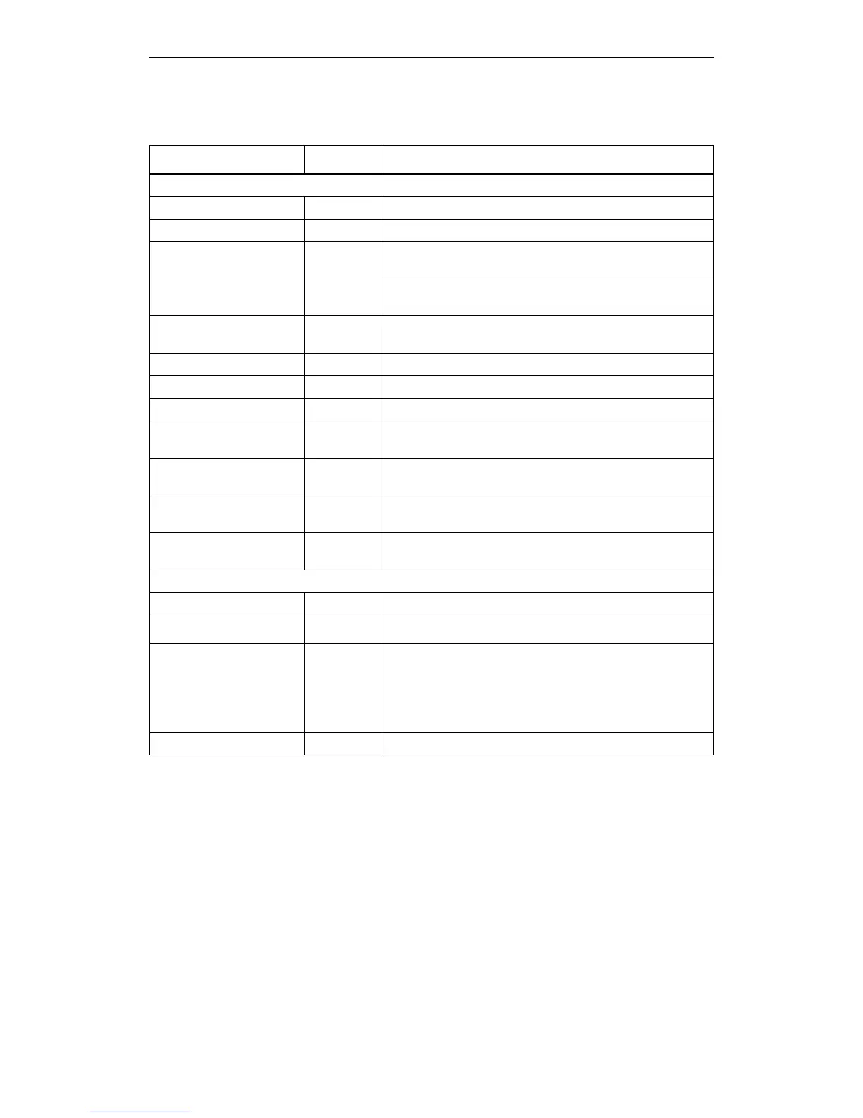
Table 3-1 Meaning of the displays and operator controls
Name Color (LED) Meaning
Displays
POWER Green Ready to run
SYNC Green SICLOCK TC 400 has been externally synchronized
FAULT Red Alarm
The associated message text is shown in the display.
Flashing red Warning
The associated message text is shown in the display.
LINK (Port 1-4) Yellow Physical connection has been established, possible to send
and receive
ACTIVE (Port 1-4) Green Display of the data traffic for the respective port
RADIO CLOCK 1 Yellow Receive signal of radio clock 1
RADIO CLOCK 2 Yellow Receive signal of radio clock 2
OUT 1 Green Output 1
Output signal at the terminal
OUT 2 Green Output 2
Output signal at the terminal
OUT 3 Green Output 3
Output signal at the terminal
Display Display of time, date and synchronization or message text
when an error occurs
Operator controls
SETUP Call of the password input or parameter list
↑ ↓ ← →
Navigation in the menus
ESC • Cancellation of an entry and return to the call menu.
• Switchover from an information message or warning to the
mode display
• Change to operator control for a limited period when a per-
sistent message is pending.
OK Accepting of entries and acknowledging of messages
 Loading...