Parameterization and Operation on the Device
8-68
© Siemens AG 2007 All Rights Reserved
SICLOCK
®
TC 400
8.1 Operating display
When the device is switched on, there is no operating and status display for a
short ramp-up time.
Figure 8-2 Display of the device ramp-up after switching on
The time, date and the current synchronization status are displayed during oper-
ation.
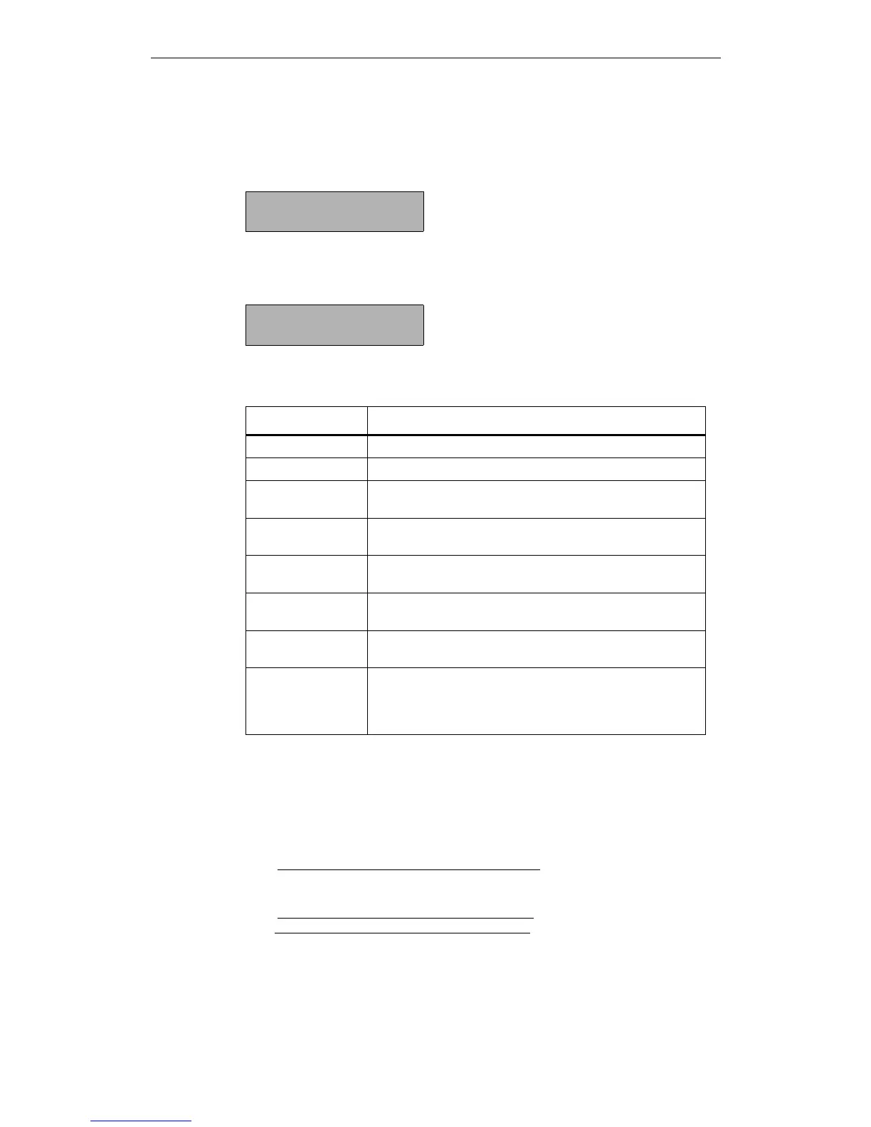
Figure 8-3 Example of the display during operation
SICLOCK TC 400
......
09:48:26 →NTP
Tue, 19. Sept 2007
Table 8-1 Possible synchronization states
Display Meaning
→Q No external synchronization
→NTP External synchronization via NTP is active
→DCF1
1)
→DCF2
1)
External synchronization via DCF signal at RADIO CLOCK 1
or RADIO CLOCK 2 is active
→GPS1
1)
→GPS2
1)
External synchronization via GPS signal at RADIO CLOCK 1
or RADIO CLOCK 2 is active
→MBG1
→MBG2
External synchronization via Meinberg telegram at RADIO
CLOCK 1 or RADIO CLOCK 2 is active
→NME1
→NME2
External synchronization via NMEA telegram at RADIO
CLOCK 1 or RADIO CLOCK 2 is active
→SER1 flashing
→SER2 flashing
Currently a valid serial telegram is not being received
--1 flashing
2)
--2 flashing
2)
The external synchronization at RADIO CLOCK 1 or RADIO
CLOCK 2 has not supplied a signal for longer than 30 min
(default setting) and there has been no switchover yet to a
substitute synchronization.
1) If the display is flashing, currently no valid signal is being received.
2) This is the case when the timeout for the switchover to the substitute synchroniza-
tion has been selected larger than the monitoring timeout of the external synchroni-
zation.
The timeout for the switchover to the substitute synchronization can be set via the
following parameter entry:
/Redundancy/Redundancy/timeout (0.09.10)
The timeout of the external synchronization can be set via the following parameter
entry:
/Inputs/Input 1/Monitoring/timeout (0.20.01) or
/Inputs/Input 2/Monitoring/timeout (0.21.01)
 Loading...