Diagnostics Using the User Program
10-14
DP/PA Link and Y Link Bus Couplings
A5E00193841-011
10.2.6 Interrupts
The interrupt section provides information on the interrupt type and the event that
triggered the interrupt. The interrupt section is only transmitted if an interrupt is
present
Structure of the interrupt section
The structure of the interrupt section depends on which DP master the IM 157 is
being operated on:
On a DPV1-capable DP master, the interrupt section consists of a maximum of
63 bytes.
On a redundant S7 master not capable of DPV1, the interrupt section consists
of 20 bytes.
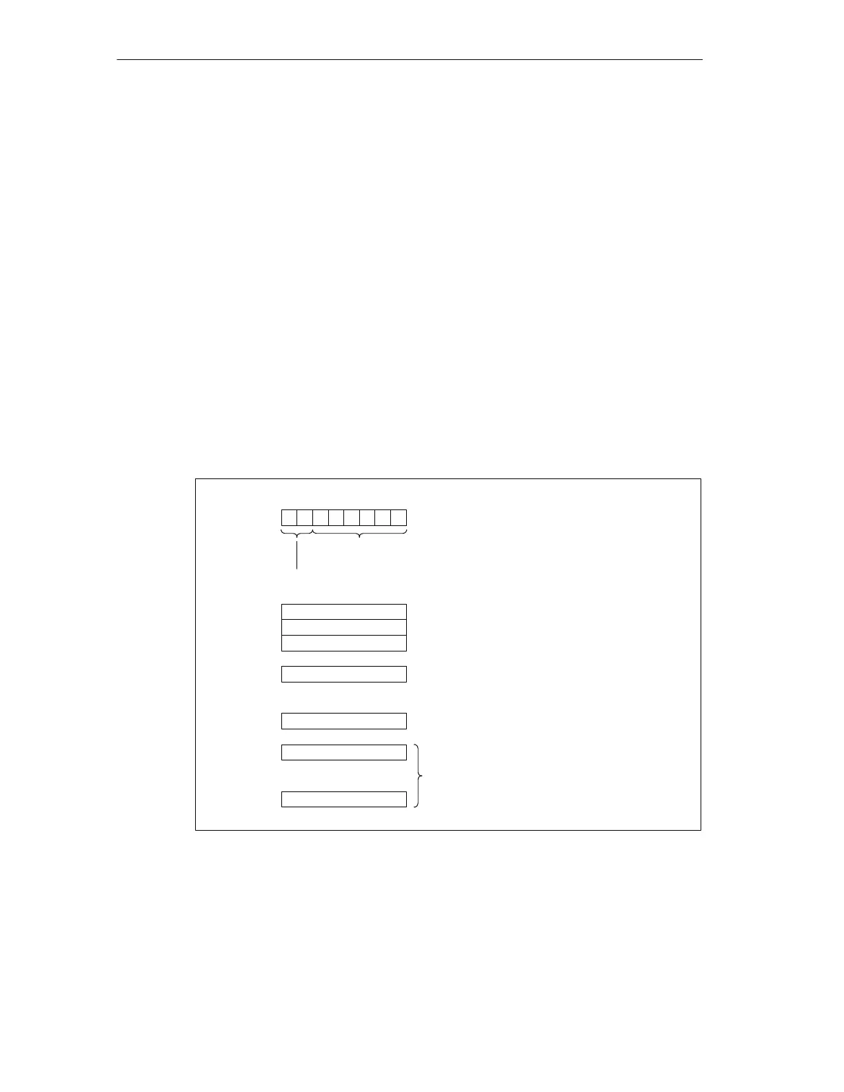
Structure of the interrupt section on the redundant S7 master that is not capable
of DPV1
Byte 168
Bit no.
Length of the diagnostic blockincluding byte 168 (= 20 bytes)
Code for station diagnosis
7
6543210
00010100
Byte 169
01
H
Interrupt type: diagnostic interrupt
Byte 170
Slot number of the IM 157
Byte 171
01
H
: incoming error
02
H
: outgoing error
Byte 187
.
.
Byte 174
02
H
Byte 172 00
H
: no fault
05
H
: module fault (error detected on underlying
master system)
Byte 173
0B
H
Reserved
00
H
00
H
.
.
Reserved
Figure 10-8 Structure of the interrupt section on the redundant S7 master that is not
capable of DPV1

 Loading...


