Installation
3-10
DP/PA Link and Y Link Bus Couplings
A5E00193841-011
IM 157 product release
For redundant operation, both IM 157 modules must have the same order number
and the same product release.
If the IM 157 (-0AA82-) is employed as a spare part for a precursor module, it can
also be used in the Y link together with an IM 157 with the order number -0AA81-.
Installing bus modules and modules
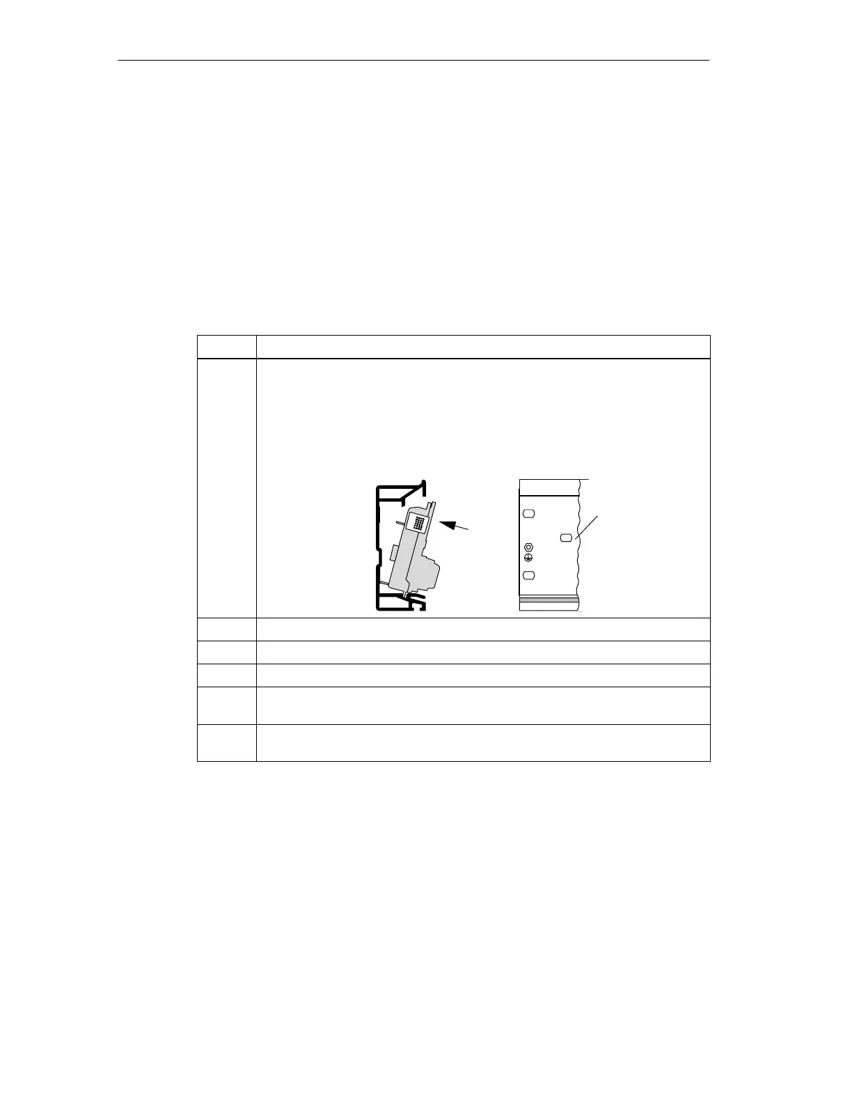
Install and remove the bus modules in a deenergized state as follows:
Step Activity
1
Hook the lower edge of the BM IM/IM bus module onto the rail, press it into
the rail (a) and push it to the left until it engages (b).
If you are using the 530 mm DIN rail and position the BM IM/IM in the
right-hand latched position, you can install two additional PS 307; 2A or one
PS 307; 5A to the left of the bus module.
Latched
position
a
b
2 Hook the BM Y coupler bus module onto the rail and press it down onto the rail.
3 Push the bus modules together so that the module connectors are in contact.
4 Insert both IM 157 in the BM IM/IM bus module.
5 Insert the Y coupler in the BM Y coupler bus module. Use the side guides of the
bus modules to do this.
6 Tighten the bolts of the modules to secure them. This also fixes the bus
modules to the rail.

 Loading...


