5-3
Box PC 820 / PC FI45 V2, Manual
A5E00051531-03
5.2 Design and Mode of Operation
The bus board is designed as a passive link between the motherboard and the
expansion modules. It is mounted by means of two screws.
The bus board has two ISA slots and two PCI slots, as well as a shared ISA/PCI
slot. The expansion modules are powered via the link between the bus board and
the motherboard. An external power supply (+5V and +12V) is provided.
X8
X7 (shared PCI Slot 3)
X6 (shared ISA Slot 3)
X5 (ISA Slot 2)
X4 (ISA Slot 1)
X3 (PCI Slot 2)
X2 (PCI Slot 1)
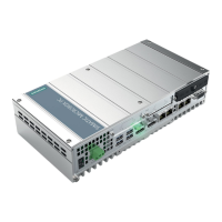
Figure 5-1 Bus Board
Bus Board
Siemens Distributor